DSP Based Equalization for 40-Gbps Fiber Optic Communication
110 likes | 236 Vues
DSP Based Equalization for 40-Gbps Fiber Optic Communication. Shahriar Shahramian. Problem & Motivation. At high bit rates (> 10 Gbps) fiber optic channel’s impairments become prominent.

DSP Based Equalization for 40-Gbps Fiber Optic Communication
E N D
Presentation Transcript
DSP Based Equalization for 40-Gbps Fiber Optic Communication Shahriar Shahramian
Problem & Motivation • At high bit rates (> 10 Gbps) fiber optic channel’s impairments become prominent. • Differential Mode Dispersion (in Multi Mode Fiber) & Polarization Mode Dispersion (in Single Mode Fiber) degrade signal quality over long haul fiber channels. • Equalization techniques are required to achieve high bit rate over fiber optic channels.
Problem & Motivation II • Some analog equalization techniques have been shown for 40-Gbps communication. • Another possibility for equalization is digital equalization. • The main challenge of high speed digital equalization is the design of the ADC at such high bit rates. • Provided that high speed ADCs can be built, digital equalization is more accurate and offers more flexibility.
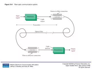
DSP Equalizer Block Diagram Optical Fiber Equalized Data Detector & Pre-Amp Ultra Fast ADC (40-GS/s) Adaptive Channel Equalizer Clock Recovery DFE Adaptive Channel Equalizer FFE + Slicer -
Flash ADC Block Diagram Input Stage Track & Hold Data Tree T/H TIA INV TH DRV 16 1 16 S/H Clock Comparators (16) Thermometer Code Output Latch Offset Amp. INV INV GAIN Clock Tree 16 External Clock 1 16
THA Block Diagram Input Stage Track & Hold Output Driver T/H TIA INV TH DRV DRV Clock Distribution TIA INV INV CLK DRV
DC & Biasing Input THA Die Photo • Chip Area: • 1.1mm2 • Technology: • 0.18μm SiGe BiCMOS HBT • 150/155 GHz fT/fmax • Foundry: • Jazz Semiconductor Data Input (DC – 20 GHz) Data Output Clock Input (40 GHz)
THA Measurement Results • Both data and clock input have been applied single ended. • In Differential mode, the “in phase” clock feed-through signal is eliminated. OP Diff. Output OP ON Diff. Output
THA Measurements II • Two tone signals at the input (separated by 100 MHz) have been used to measure the IM3 output power and the input compression point. • An abstract has been submitted to CSICS 2005 based on this circuit as (to our best knowledge) the world’s fastest THA.