Download
1 / 38
380 likes | 467 Vues
This overview covers the developments in the ILC project as of 2013, highlighting technical news, management changes, key milestones, and the path forward. It discusses progress in XFEL construction, high-gradient cavity production, cryomodule assemblies, and the site-dependent design for the future. The text provides insights into the challenges faced, collaborations, and the technical focus for the next three years. Stay informed about the latest advancements in this international project.

E N D
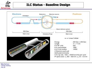
Status of ILC Project Nick Walker – DESY ILD Meeting – Cracow – 24.09.2013
Overview • The GDE is over! • Technical news: XFEL (ILC prototype) construction • Beyond TDR: • Under new management: LCC • Beginnings of a 3-year technical programme • Light Higgs Factory & 10-Hz running • Where do we go from here?
GDE Timeline 2014 2005 2006 2007 2008 2009 2010 2011 2012 2013 LHC physics GDE LCC Reference Design Report (RDR) Tech. Design Phase (TDP) 1 TDP 2 TDR published ~250 FTE per year (avg) ~2,000 MY ( ~5,000 if pre-GDE included) ~300 M$ globally Global Event June 12 Tokyo Fermilab CERN
Worldwide Cryomodule Development CM1 at FNAL NML module test facility S1 Global at KEK SRF Test Facility (STF) PXFEL 1 installed at FLASH, DESY, Hamburg now commencing XFEL production
European XFEL @ DESY • Largest deployment of this technology to date • 100 cryomodules • 800 cavities • 17.5 GeV ~25 MV/m The ultimate ‘integrated systems test’ for ILC.
Quest for high gradients TDR published result • GDE worldwide R&D effort to establish high-gradient cavity production • 6 Now qualified cavity vendors • XFEL (mass) production • large (~800) unbiased statistical sample • 2 vendors • Currently ~10% tested • critical for ILC
XFEL cavity production status As of 11.09.2013 Num. of cavities: vendor 1 23 vendor 2 56 2nd pass: additional high-pressure rinse usable gradient: X-ray limited (dark current) Maximum gradient
XFEL Cryomodule Assembly XM-3 tested @ DESY XM-2 cool down @ DESY XM-1 assembly @ Saclay XM+1 prep @ Saclay XM+.. XM+101 Module assembly at CEA Saclay Just starting 1 CM / 2 weeks Peak rate: 1 CM / 1 week (possibly 1.5 CM / 1 week)
XM-3 Result Average quench: 33.4 MV/m ILC XFEL An ILC spec cryomodule! Heat loads < expected 7 Large Grain cavities Qualification of Saclay assembly facility
ILC Organisation Technical Board Hitoshi Hayano– KEK (deputy) Kirk Yamamoto – KEK NobuhiroTerunuma – KEK Marc Ross – SLAC NikolaySolyak – FNAL Olivier Napoly – CEA Saclay Nick Walker – DESY Akira Yamamoto – KEK LC Office
ILC Organisation Technical Board Hitoshi Hayano– KEK (deputy) Kirk Yamamoto – KEK NobuhiroTerunuma – KEK Marc Ross – SLAC NikolaySolyak – FNAL Olivier Napoly – CEA Saclay Nick Walker – DESY Akira Yamamoto – KEK LC Office ILC Group Structure for the LCC phase ? coming soon! Work for TB at LCWS - Tokyo
LCWS Working Groups Linear Collider Groups Joint ILC-CLIC groups ILC-specific AWG1: Sources Wei Gai (ANL) Steffen Doebert (CERN) Masao Kuriki (KEK) AWG2: Damping Rings IoannisPapaphilippou (CERN) David Ruben (Cornell) AWG3: Beam Delivery & MDI Rogelio Tomas (CERN) Tom Markiewicz (SLAC) GaoJie(IHEP) Lau Gatignon (CERN) AWG7: Conventional Facilities Vic Kuchler (FNAL) John Osborne (CERN) Atsushi Enomoto (KEK) AWG9: SCRF Technologies Akira Yamamoto (KEK) Hitoshi Hayano(KEK) Wolf-Dietrich Moeller (DESY) AWG4: Beam Dynamics NikolaySolyak (FNAL) Andrea Latina (CERN) Kiyoshi Kubo (KEK) AWG8: System tests and performance studies Daniel Schulte (CERN) Marc Ross (SLAC) Roberto Corsini (CERN) NobuhiroTerunuma (KEK)
Technical focus will be: The Next Three Years • Site-dependent design (Kitakami) • Further R&D • SRF infrastructure, mass production, coupler design • Positron source • BDS (ATF2) • … • Pre-implementation project studies • ILC cryomodule production in all three regions • International project structure and project tools development
Site dependent design • Understanding constraints from the Kitakami site • Specific geological and topographical issues • Infrastructure and support planning • Modifying the TDR design as necessary • Expect to be driven by Conventional Facilities and Siting • Example: shifting main linac access ways • Detector hall and “central region” will likely be a focus • Considerations of a staged approach • starting at 250 GeV centre of mass Not discussing change of scope!
TDR: Japanese site-dependent design Challenges of a mountainous terrain Long horizontal access tunnels (≤ 1 km) Almost entirely under ground installation LCC forming plans for site-dependent study LCWS will be an important meeting in this regard
Final Focus R&D: ATF2 @ KEK Formal international collaboration
Final Focus R&D: ATF2 @ KEK • Test bed for ILC final focus optics • strong focusing and tuning (37 nm) • beam-based alignment • stabilisation and vibration (fast feedback) • instrumentation March 2013: <65 nm achieved (g scaling to 250 GeV ~5nm) IP beam size monitor A major challenge at 1.3 GeV
Staged construction: 250 GeV • Complete civil construction for 500 GeV machine • Install ~1/2 linacs for fist stage operation (and long transport line) • Capital savings ~25% • Adiabatic energy upgrade (lower rate cryomodule production) Favouredby Japan
ILC Published Parameters Luminosity Upgrade Centre-of-mass independent: http://ilc-edmsdirect.desy.de/ilc-edmsdirect/item.jsp?edmsid=D00000000925325
ILC Published Parameters Centre-of-mass dependent: http://ilc-edmsdirect.desy.de/ilc-edmsdirect/item.jsp?edmsid=D00000000925325
ILC Published Parameters Centre-of-mass dependent: http://ilc-edmsdirect.desy.de/ilc-edmsdirect/item.jsp?edmsid=D00000000925325
Luminosity Upgrade Adding klystrons (and modulators) Damping Ring:
ILC Published Parameters Centre-of-mass dependent: http://ilc-edmsdirect.desy.de/ilc-edmsdirect/item.jsp?edmsid=D00000000925325
Higgs Factory Centre-of-mass dependent: http://ilc-edmsdirect.desy.de/ilc-edmsdirect/item.jsp?edmsid=D00000000925325
ILC Polarised-Positron Production e- linac Uses primary electron beam to generate ~30 MeV photons in a SC helical undulator Photons converted into e+e- pairs in “thin” titanium target Positron production yield dependent on e- beam energy (and therefore Ecm) e- to IP
Positron Yield Ebeam = 125 GeV 147m helical undulator(TDR baseline) design point yield margin Wei Gai (ANL) et al
TDR: 10-Hz Mode (e+ production) • For TDR, we are required to have solutions down to Z-pole (~45 GeV beam) • ILC TDR assumes 10-Hz mode where • e- linac is pulsed at 10 Hz • first pulse @ 150 GeV to make positrons • second pulse @ Ecm/2 to make luminosity • Issues • DR damping time halved (extra cost and MW) • Beam dynamics in Main Linac (looks OK) • Additional beam lines and pulsed magnet systems • Additional AC power for elec linac 10-Hz mode • But for 500 GeV design, additional power already available • Not insignificant cost increase for a dedicated LHF collision rate still 5Hz
Positron Yield Ebeam = 125 GeV 147m helical undulator(TDR baseline) design point yield margin Wei Gai (ANL) et al
Positron Yield for a LHF Ebeam = 125 GeV Recover yield by going to ~250 m of undulator yield margin Wei Gai (ANL) et al
Alternative Electron-Driven Source Will be a focus of study during the LCC phase T. Omori et al, Nucl. Instrum.Meth.A 672(2012) 52-56
Light Higgs Factory • Assume we do not need 10-Hz e+ production mode • PAC ~ 120 MW ~100 MW (at least for undulator) • TDR still contains • 10 Hz damping ring (100 ms store time) • 10 Hz e+e- source and injectors • Could we run 10 Hz collisions?
Higher rep rate running Not part of TDR scope! lumi factor: x2 x1.4 x1 reducing ML gradient issues for detectors? Snowmass scenario: http://arxiv.org/abs/1308.3726
Issues for LHF 1st stage? • Shorter linacs run at full gradient (31.5 MV/m) • 10Hz operation would require additional AC power • x2 RF AC power • x1.5 Cryo power • Requires feasibility study • e.g. cryoplant capacity • cost! Beyond TDR baseline!! Something to talk about
Snowmass Scenario • http://arxiv.org/abs/1308.3726 Phase 1 250 GeV L=0.75×1034 Phase 2 500 GeV L=1.8×1034 Phase 3 500 GeV L=3.6×1034 (lumi upgrade) Phase 3 250 GeV L=3.0×1034 (lumi upgrade @ 10Hz) TDR baseline scope & parameters
Next Steps • (Wait for Japan!) • Develop a technical plan for the next three years • Site-dependent design study • Specific Industrialisation and cost-reduction R&D • Work closely with XFEL and monitor progress • Begin to discuss possible contributions to a Japanese hosted projected • Scope of in-kind contributions • Project structure • … • Establish European, American and Asian Regional Teams in the post-GDE era Funding!