Download

1 / 24
250 likes | 403 Vues
SLAC Particle Sources Efforts Review/Status and Plans. SLAC HEP Program Review June 13 th , 2007. Electron Source Systems. Laser. Injector specific RF structures. Photo cathodes. Gun. Positron Source Systems. e+/e- Institutions in the US. SLAC Overall coordination & leadership

E N D
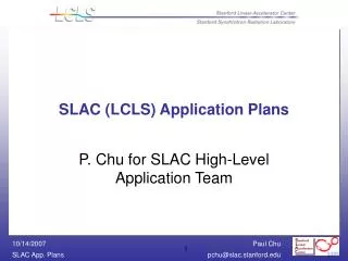
SLAC Particle Sources EffortsReview/Status and Plans SLAC HEP Program Review June 13th, 2007
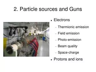
Electron Source Systems Laser Injector specific RF structures Photo cathodes Gun
e+/e- Institutions in the US • SLAC • Overall coordination & leadership • Define parameters • Polarized e- Source Laser System • Photocathode Development • Target hall, remote handling, activation • Beamline optics and tracking • NC L-Band accelerator structures and RF systems • Experiments – E166, FLUKA validation experiment • LLNL • Target simulations • Target design • Pulsed OMD design • ANL • Optics • Tracking • OMD studies • Eddy current calculations • Jlab • Polarized gun development • Cornell • Undulator design, alternative target concepts
Collaborating non-US Institutions • Institutions doing substantial work on ILC baseline e+ development • CCLRC-Daresbury • undulator design and prototyping • beam degradation calculations • CCLRC-RAL (?) • remote handling • eddy current calculations • target hall activation • Cockcroft and Liverpool University • target design and prototyping • DESY-Zeuthen • target hall activation • spin preservation • photon collimation • E166
Electron Source Technical Milestones • Demonstrate Source Laser System. • DC Gun Development (HV design). • Advance Polarized Photocathode Technology. • Bunching system design. • Beam Dynamics. • Demonstrate polarized electron bunch train with ILC parameters.
Source Laser System • Source laser development has started at SLAC’s ILC Injector Development Facility. • Laser system pushes the state of the art in laser technology. • Collaboration with Kapteyn-Murnane Labs through SBIR phase II (pending approval) aids in laser development. • Facility allows use of SLC 120 kV DC gun in combination with laser system to generate polarized ILC electron bunch train. • Goal is to demonstrate the operating laser system by the end of FY 09.
DC Gun Development • Project will start in FY 08 at Jlab. • 140 kV minimum operating voltage 200 kV design. • Combine features of SLAC’s 120 kV SLC gun and Jlab’s 100 kV gun. • HV design (power supply). • Optimize electrodes (material and design) for ILC conditions. • Load lock is essential for high reliability. • Goal is to test the gun with laser system developed at SLAC.
Photocathode R&D Program • Supported by ILC (mostly FTE’s, small M&S contribution) • Several SBIR’s/STTR’s in FY07 (all Phase I): • Activation Layer Stabilization of High Polarization Photocathodes in Sub-Optimal RF Gun Environments. • High Polarization and High Peak Current Compositionally Graded AlGaAs/GaAs Superlattice Photocathodes for RF Gun Applications. • High Polarization and High Robustness Antimonide Based Superlattice Photocathodes for RF Gun Applications. All applicable to DC guns as well • Collaboration with University of St. Petersburg (Russia): • Study of AlInGaAs/AlGaAs cathodes Baseline Design Strained GaAs/GaAsP • R&D goals: • Improve robustness and lifetime • Investigate alternative materials with • increased polarization and QE • Maintain and build expertise
Photocathode R&D Program Faraday rotation experiment • Measures Depolarization Dynamics • Depolarization occurs during transport through cathode material • Interband absorption smearing due to bandedge fluctuations • Hole scattering between the HH and LH states causes a broadening of the LH band • Spin precession due to an effective magnetic field generated by the lack of crystal inversion symmetry and spin orbit coupling • Electron hole scattering • Less polarization selectivity in the BBR • Scattering and trapping of electrons in the BBR • SLAC-Pub-11384 • Understanding depolarization allows design of optimized photocathodes
ILC Sources Optics and beam line design Example: Electron Source Optics Positron beam line geometry
ILC Polarized Positron System Technical Milestones 1. Demonstrate undulator parameters. 2. Demonstrate NC SW structure high power rf performance. 3. Spinning target pre-prototype demonstration. 3. Eddy current measurements on spinning target. 4. Selection and Technical design of Optical Matching Device. 5. System engineering for e+ source remote handling. 6. System engineering for photon dump. 7. System design compatibility with ILC upgrade scenarios: polarization and energy.
Undulator Challenges • High fields • Pushing the limits of technology • Short Periods • Shorter periods imply higher fields • Narrow apertures • Very tight tolerances - Alignment critical • Cold bore (4K surface) • Cannot tolerate more than few W of heating per module • Minimizing impact on electron beam • Must not degrade electron beam properties but have to remove energy from electrons • Creating a vacuum • Impossible to use conventional pumps, need other solution • Minimizing cost • Minimize total length, value engineering
UK 4m Prototype Module 50K Al Alloy Thermal shield. Supported from He bath U beam Support rod Stainless steel vacuum vessel with Central turret Stainless Steel He bath filled with liquid Helium. Magnet support provided by a stiff U Beam Beam Tube Superconducting Magnet cooled to 4.2K Construction has started, will be complete by Autumn 07
Undulator Magnet Design Concept Winding pins Steel Yoke. Provides 10% increase in field and mechanical support for former PC board for S/C ribbon connections Steel yoke 2 start helical groove machined in steel former Cu beam pipe, withconductor wound on to tube OD
Baseline Target Design • Wheel rim speed (100m/s) fixed by thermal load (~8% of photon beam power) • Rotation reduces pulse energy density from ~900J/g to ~24J/g • Cooled by internal water-cooling channel • Wheel diameter (~1m) fixed by radiation damage and capture optics • Materials fixed by thermal and mechanical properties and pair-production cross-section (Ti6%Al4%V) • Wheel geometry (~30mm radial width) constrained by eddy currents. • 20cm between target and rf cavity. T. Piggott, LLNL
Activation Simulations • New target geometry (mostly) migrated to FLUKA • Simulations will begin at DL shortly as well as DESY/Z motor assembly L. Fernandez-Hernando, DL NC rf cavity target wheel (including water channel)
Experiments at SLAC • E166 – proof of principle: Undulator based polarized positron production • Publication is pending (NIM, PRL) • Validation of FLUKA activation calculations • SLAC/CERN Collaboration (RP groups) • 100 W • 30 GeV electron beam in ESA at SLAC • Cylindrical copper dump • Samples around the dump (including a Ti-4V-6Al) • Look mr/hour and gamma spectrum from irradiated samples • Data taken, analysis in progress • http://www-group.slac.stanford.edu/esh/rp/rpg/T-489
Optical Matching Device • Optical Matching Device • factor of 2 in positron yield (3 if immersed target) • DC solenoid before target or pulsed flux concentrator after target • Pulsed device is the baseline design • Target spins in the magnetic field of the OMD • Eddy currents in the target – need to calculate power • Magnetic field is modified by the eddy currents – effect on yield?? • Eddy current mitigation • Reduce amount of spinning metal • Do experiment to validate eddy current calculations • Look for low electrical / high thermal conductivity Ti-alloys • Other materials such as ceramics • No OMD • Use focusing solenoidal lens (1/4 wave) – lower fields • OMD is upgrade to polarization!!!!!
Eddy Current Experiment Proposed experiment Layout at Cockcroft Institute/Daresbury (this summer) Eddy current calculation mesh - S. Antipov, W. Liu, W. Gai - ANL
Prototype Positron Capture Section Design and Prototype High Power Test using L-band station in SLAC’s Endstation B
Outlook – EDR phase for e-/e+ Dec 07: EDR Scope definition: design depth and breadth, cost, schedule, staff Dec 09: Freeze layout, full component and civil specifications Jan 09: EDR detailed component inventory May 09: First cost review Dec 09: Deliver EDR and preconstruction work plan Need Systems Engineering in FY08