Transverse Impedance from Collimator Bench Measurements Using 1 Wire
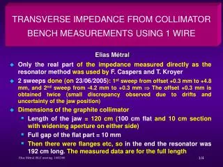
This study presents the measurement of transverse impedance using a resonator method to analyze collimator characteristics. Two sweeps were conducted from +0.3 mm to +4.8 mm and -4.2 mm to +0.3 mm, revealing minor discrepancies due to positional uncertainties. The graphite collimator, measuring 192 cm in total length, demonstrated a full gap of 10 mm in the flat part. Measurements covered a frequency range from 57 MHz to 1.4 GHz, showing results parallel to previous findings. These measurements could not validate the new inductive bypass formalism due to frequency limitations.

Transverse Impedance from Collimator Bench Measurements Using 1 Wire
E N D
Presentation Transcript
TRANSVERSE IMPEDANCE FROM COLLIMATOR BENCH MEASUREMENTS USING 1 WIRE Elias Métral • Only the real part of the impedance measured directly as the resonator method was used by F. Caspers and T. Kroyer • 2 sweeps done (on 23/06/2005): 1st sweep from offset +0.3 mm to +4.8 mm, and 2nd sweep from -4.2 mm to +0.3 mm The offset +0.3 mm is obtained twice (small discrepancy observed due to drifts and uncertainty of the jaw position) • Dimensions of the graphite collimator • Length of the jaw = 120 cm (100 cm flat and 10 cm section with widening aperture on either side) • Full gap of the flat part = 10 mm • Then there were flanges etc, so in the end the resonator was 192 cm long. The measured data are for the full length
Driving + detuning impedance Deduced from measurements From theory (only the 1 m long flat part)
MEASURED LONGITUDINAL IMPEDANCE VS. TRANSVERSE OFFSET 20 pictures (from 57 MHz to 1.4 GHz)
Conclusion • Results very similar to the ones already obtained by FZ on 17/07/05 • These measurements CANNOTCONFIRM that the new formalism (with the “inductive bypass”) is true, as the frequency range is too high (from 57 MHz to 1.4 GHz) Classical regime only! Interesting frequency range