Download
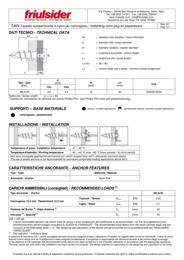
1 / 6
60 likes | 257 Vues
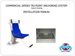
COMMERCIAL SERIES TRI-POINT ANCHORING SYSTEM Patent Pending. INSTALLATION MANUAL. COMMERCIAL SERIES TRI-POINT ANCHORING SYSTEM INSTALLATION Patent Pending PARTS LIST 1 - Anchor Plate with bonding Lug 3 - 5/8 Stainless Steel Bolts 3 - 6” Anchoring Rods.

E N D
COMMERCIAL SERIES TRI-POINT ANCHORING SYSTEM Patent Pending INSTALLATION MANUAL
COMMERCIAL SERIES • TRI-POINT ANCHORING SYSTEM INSTALLATION • Patent Pending • PARTS LIST • 1 - Anchor Plate with bonding Lug • 3 - 5/8 Stainless Steel Bolts • 3 - 6” Anchoring Rods
ANCHORING PLATE, ANCHORS & BONDING LUG 5/8’s Bolts
TRI POINT ANCHOR INSTALLATION – COMMERCIAL SERIES • Anchor Plate’s front edge should be no closer than 17” to the pool wall • Attach copper wire to the bonding lug and then to your bonding grid • Cold Pin’s should be ½” rebar 6” to 8” long Water Pool Wall Minimum 17” Distance From pool wall Overview 3’ Anchor Plate Section Detail 3’ 3’ 6” Threaded Anchor’s Cold Pin 6” Bonding Lug Cold Pin Concrete Concrete SAND 5/8 Bolts
Step 1: Determine the location for installation (Make sure all ADA requirements are met) • Step 2: Make sure that all the parts are present (Refer to the parts list) • 1 - Anchor Plate with Bonding Lug • 3 - 5/8 Stainless Steel Bolts • 3 - 6” Anchors • Step 3: At the determined location for installation, chalk out a 3’ X 3’ area prior to cutting out the concrete. (Refer to overview, the front end of the Anchor Plate must be no more than 17” from the pool wall and at least 6” deep). • NOTE: Contact Qualified Contractor for installation! • Step 4: Once the 3” X 3” area is cut out, make sure you drill in the inner wall of all 4 sides of the area (refer to the section detail) for the purpose of cold pinning the new concrete to the old concrete. Use 1/2” rebar, 6” to 8” in length. • Step 5: Attach the 3 – 6” threaded anchor’s with the 5/8’s bolts (included) to the Anchor Plate and tighten down.
Step 6: Place the Anchor Plate in the area, make sure that the front of the Anchor Plate is no less than 17” from the pool wall. (refer to overview) A key element is to make sure that the Anchor Plate is level and square with the pool so that your Commercial Series Lift sits properly on the deck. Step 7: Grounding the unit – The bonding lug is already installed on the Anchor plate (furthest point from the pool wall on the Anchor Plate) locate the bonding lug, attach at a minimum 14 – 16ga copper wire and then attach to your bonding grid. NOTE: Contact electrician to make sure you comply with the BONDING CODES. Step 8: Pour in your concrete, (make sure you cover the holes in the 3 threaded anchor’s so you don’t get concrete in the threads) minimum of 4,000 psi with reinforcing rod. Also make sure that the tops of the threaded anchors are flush with the deck. Before you install your lift make sure you let the concrete set up for 48 hours. Step 9: After the concrete has set for 48 hours, now it’s time to install your lift. Place your Commercial Series Lift over the anchor holes, screw in the Anchor bolts that are included and tighten down securely. Once you have completed the installation, please refer to User’s Manual for a safe operation.