Download

1 / 27
460 likes | 2.15k Vues
Hydraulic Structures in Irrigation Distribution Systems. Chapter 5. Valves in pipe networks. On-Off valves Throttling valves Pressure Regulating Valves Check Valves Surge Control Valves Pressure Relief Valves Vacuum relief valves (Air release valves. Pressure regulating valve.

E N D
Hydraulic Structures in Irrigation Distribution Systems Chapter 5
Valves in pipe networks • On-Off valves • Throttling valves • Pressure Regulating Valves • Check Valves • Surge Control Valves • Pressure Relief Valves • Vacuum relief valves (Air release valves
Flow measurements in pipelines • differential pressure flow meters • Venturi meters • Orifice meters • Elbow meters Rotating mechanical flow meters Bypass flow meters Ultrasonic flow meters Magnetic Flow meters
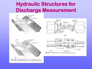
Control structures in open channels • Intake structures • Check structures • Check-drops • Drop and chute structures
Flow measurements in open channels • Volumetric method • Velocity area method • Using float method • Current meters • Control sections • Thin plate weirs • Broad Crested weirs • Flumes
Assumptions • no head losses (E1 = E2) (the means no significant turbulence) • water surface elevation remains constant, note: this is physically impossible, but actual errors are small • pressure at crest (station 2) = Patmo throughout depth.
For Cd=0.611, weir equation becomes: • For SI units, g= 9.81 m/s2, or • For foot units, g=32.2 ft/s2, or • In general, discharge could be given by: • Where, C is a weir coefficient.
Weirs • Advantages: • Accurate measurement. • Simple and easy to construct with non-obstruction by moss (type of algae) or floating materials. • Durable • Disadvantages: • Require considerable fall of water surface. • Deposition of sand, gravel and silt upstream of weirs
Example • An end-contracted weir of total length 286 ft and crest height 5 ft is used to discharge water without exceeding a head of 2.5 ft from a tank 300 ft wide. The weir carries piers that are 10 ft clear distance apart and 2 ft wide, to support the footway. Determine the discharge. Cd = 0.6