Chapter 4. Interconnecting Multiple OSPF Areas
Chapter 4. Interconnecting Multiple OSPF Areas. Table of Contents. Multiple OSPF Areas OSPF Operation Across Multiple Areas Using and Configuring OSPF Multiarea Components Verifying OSPF Operation Summary. Multiple OSPF Areas. Types of Routers Types of Link-State Advertisements

Chapter 4. Interconnecting Multiple OSPF Areas
E N D
Presentation Transcript
Table of Contents • Multiple OSPF Areas • OSPF Operation Across Multiple Areas • Using and Configuring OSPF Multiarea Components • Verifying OSPF Operation • Summary
Multiple OSPF Areas • Types of Routers • Types of Link-State Advertisements • Types of Areas
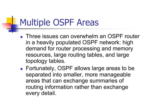
Large OSPF Network Issues OSPF The SPF is running too often for me to route. I am only receiving LSAs, no data. OSPF OSPF OSPF OSPF My routing table is too big, I am running low on memory.
OSPF Hierarchical Routing Area 0 Area 1 Area 2 Autonomous System • AS(autonomous system)와 Area로 구성된다. • Routing Update Traffic을 최소화 한다.
Large OSPF Network Issues • SPF Algorithm에 의한 빈번한 재계산 => 많은 CPU Cycle을 사용한다. • Large Link State Table => 많은 Memory를 사용한다. • Large Routing Table => 많은 Memory를 사용한다. • 참고: routing table entry당 200~280bytes, extra는 44byte추가 Solution : OSPF Hierarchical Routing • SPF Calculation의 빈도를 줄인다. • 작은 Routing Table을 유지한다. • LSU(link-state update) overhead를 줄인다. OSPF Design Guidelines • Routing Domain의 Area 수 : Min 1, Mean 23, Max 60 • Single Area의 Router 수 : Min 20, Mean 160, Max 350 • Routing Domain의 Router 수: Min 20, Mean 510, Max 1000
Area 1 Backbone Area 0 Area 2 ABR and BackboneRouter Backbone/InternalRouters InternalRouters InternalRouters ASBR andBackbone Router ABR and BackboneRouter ExternalAS Types of Routers • Internal Router • Backbone Router • ABR(Area Border Router) • ASBR(Autonomous System Boundary Router)
Types of Link-State Advertisements • LSA Type 1 : Router Link Entry : O-OSPF : Router Link States : Internal Router에 의해 발생된다. • LSA Type 2 : Network Link Entry : O-OSPF : Net Link States : Multi-access Network 상의 DR이 발생시킨 LSA이다. • LSA Type 3 : Summary Link Entry : IA-OSPF InterArea : Summary Net Link States, • ABR에 의해 발생된 Summary LSA이다. • LSA Type 4 : Summary Link Entry : IA-OSPF InterArea : Summary ASBRLink States :ASBR에 의해 발생된 OSPF Summary LSA이다. • LSA Type 5 : AS External Link Entry : E1-OSPF External Type 1, E2-OSPF External Type 2 : AS External Link States:ASBR에 의해 발생한 다른 AS에 대한 LSA이다.(통상 Redistribution을 통해서 다른 AS의 네트워크 정보를 넘긴다.) • LSA Type 7 : NSSA(Not-so-Stubby-Area) AS External link Entry: N1-OSPF NSSA External Type 1,N2- OSPF NSSA External Type 2:NSSA에 있는 ASBR에 의해 발생된 LSA이다. (통상 Redistribution을 통해서 다른 AS의 네트워크 정보를 넘긴다.)
OSPF Database Output p1r3#show ip ospf database OSPF Router with ID (10.64.0.1) (Process ID 1) Router Link States (Area 1) Link ID ADV Router Age Seq# Checksum Link count 10.1.2.1 10.1.2.1 651 0x80000005 0xD482 4 Net Link States (Area 1) Link ID ADV Router Age Seq# Checksum 10.64.0.1 10.64.0.1 538 0x80000002 0xAD9A Summary Net Link States (Area 1) Link ID ADV Router Age Seq# Checksum 10.2.1.0 10.2.1.2 439 0x80000002 0xE6F8 • 참고 :Type 3는 Area 간 Summary Link이며, Type 4는 ASBR이 알리는 다른 AS의 OSPF Area에 대한 LSA로 ASBR이 알리는 Type 5 LSA와 구별된다.
Area 1 Area 0 DR External Network ExternalAS ASBR ABR Router Summary LSA Flooding OSPF routing table O - OSPF derived intra-area (router) IA - inter-area (summary) E1 - type 1 external E2 - type 2 external
E1 E1 E1 Calculating Costs for Summary and AS External Routes Area 1 Area 0 R1 R5 R4 R3 10 10 10 1785 1785 AS1 R 5’s Cost to: AS1 (E1) via R1 = 1815 AS1 (E1) via R3 = 1805 R 3’s Cost to: AS1 (E1) via R1 = 1795 AS1 (E1) via R3 = 1785 • E1, E2는 재분배를 통해서 넘어온 경로로 E1은 Metrics에 OSPF 자체의 Cost를 추가하며, E2는 Default가 [20]으로 OSPF 경로에 무관하게 동일한 경로 값으로 전파된다. E2가 Default이다.
R3 R3 R3 Types of External Routes • Type-2 (E2) metric • external cost only • Type 1 (E1) metric • external + internal Area 0 Area 1 R2 R2 R1 5 5 R3 R2 R1 20 cost = 20 N2 (E2) N1 (E1) N1 cost = 30 N2 cost = 20 N1 cost = 25 N2 cost = 20
Route-Map을 사용한 Backbone Router에서의 E1, E2 Redistribution router ospf 200 redistribute connected subnet route-map e1e2 route-map e1e2 permit 10 match ip address 1 set metric-type type-1 route-map e1e2 permit 20 match ip address 2 set metric-type type-2 access-list 1 permit 172.16.10.0 0.0.0.255 access-list 2 permit 172.16.11.0 0.0.0.255 interface loopback 1 ip address 172.16.10.100 255.255.255.0 interface loopback 2 ip address 172.16.11.100 255.255.255.0
Types of Areas Backbone Area 0 Totally StubbyArea Stub Area Interconnects areas; accepts all LSAs. Does not accept external LSAs. Does not accept external or summary LSAs.
IP Routing Table without any special OSPF capabilities. p1r3#show ip route Route summaries (O-IA) <Output Omitted> not using route summarization and all other routes 10.0.0.0/24 is subnetted, 15 subnets are accepted by router. O IA 10.3.1.0 [110/148] via 10.64.0.2, 00:03:12, Ethernet0 C 10.1.3.0 is directly connected, Serial0 O IA 10.2.1.0 [110/74] via 10.64.0.2, 00:31:46, Ethernet0 C 10.1.2.0 is directly connected, Serial1 O IA 10.3.3.0 [110/148] via 10.64.0.2, 00:03:12, Ethernet0 O IA 10.2.2.0 [110/138] via 10.64.0.2, 00:31:46, Ethernet0 O 10.1.1.0 [110/128] via 10.1.3.1, 00:31:46, Serial0 [110/128] via 10.1.2.1, 00:31:46, Serial1 O IA 10.3.2.0 [110/212] via 10.64.0.2, 00:03:12, Ethernet0 O IA 10.2.3.0 [110/74] via 10.64.0.2, 00:31:46, Ethernet0 O IA 10.4.2.0 [110/286] via 10.64.0.2, 00:02:50, Ethernet0 O IA 10.4.3.0 [110/222] via 10.64.0.2, 00:02:50, Ethernet0 O IA 10.4.1.0 [110/222] via 10.64.0.2, 00:02:50, Ethernet0 O IA 10.66.0.0 [110/158] via 10.64.0.2, 00:02:51, Ethernet0 C 10.64.0.0 is directly connected, Ethernet0 O IA 10.65.0.0 [110/84] via 10.64.0.2, 00:03:19, Ethernet0 p1r3# Routing Tables with Different Areas
IP Routing Table with route summarization and stub capabilities enabled. p1r3#show ip route <Output Omitted> Gateway of last resort is 10.64.0.2 to network 0.0.0.0 10.0.0.0/8 is variably subnetted, 9 subnets, 2 masks O IA 10.2.0.0/16 [110/74] via 10.64.0.2, 00:11:11, Ethernet0 Route summaries that C 10.1.3.0/24 is directly connected, Serial0 use route summarization. O IA 10.3.0.0/16 [110/148] via 10.64.0.2, 00:07:59, Ethernet0 C 10.1.2.0/24 is directly connected, Serial1 O 10.1.1.0/24 [110/128] via 10.1.3.1, 00:16:51, Serial0 [110/128] via 10.1.2.1, 00:16:51, Serial1 O IA 10.4.0.0/16 [110/222] via 10.64.0.2, 00:09:13, Ethernet0 O IA 10.66.0.0/24 [110/158] via 10.64.0.2, 00:16:51, Ethernet0 C 10.64.0.0/24 is directly connected, Ethernet0 O IA 10.65.0.0/24 [110/84] via 10.64.0.2, 00:16:51, Ethernet0 Default route to get to external O*IA 0.0.0.0/0 [110/11] via 10.64.0.2, 00:16:51, Ethernet0 a utonomous systems. p1r3# IP Routing Table with route summarization and totally stub capabilities enabled. p4r2#show ip route Gateway of last resort is 10.66.0.1 to network 0.0.0.0 10.0.0.0/24 is subnetted, 4 subnets O 10.4.2.0 [110/128] via 10.4.3.2, 00:20:43, Serial1 [110/128] via 10.4.1.1, 00:20:43, Serial0 C 10.4.3.0 is directly connected, Serial1 C 10.4.1.0 is directly connected, Serial0 Default route to get to other C 10.66.0.0 is directly connected, Ethernet0 areas and external autonomous O*IA 0.0.0.0/0 [110/11] via 10.66.0.1, 00:20:43, Ethernet0 systems. Routing Tables with Different Areas
Stub Area Resource의 절약을 위한 area로 일반적인 area들이 가지는 기능들중에서 일부 기능에 제약을 가하는 area이다. Stub area는: 1) AS-external-LSA를 외부로부터 받아들이지 않고, area border router로의 default route만으로 외부 route를 해결 2) area내에 ASBR을 가지지 않는다. 3) Stub area상으로의 virtual link를 허용하지 않는다. 4) Backbone area가 될 수 없다 5) 선택적으로는 다른 area부터의 summary-LSA의 import 또한 허가하지 않을 수도 있다. – default route만을 이용. Area 1 Inter area route Stub Area Area 0 Other AS R1 R5 R4 X 0.0.0.0 AS-external-LSA
Totally Stubby Area Stub Area의 확장은 "totally stubby areas"로 불리운다. Cisco에서, 이것은 Stub Area 설정에 "no-summary" 키워드를 더함으로써 나타낸다. Totally Stubby Area란 외부 경로(External Routes)와 축약 경로(Summary Routes; Inter-Area Routes)들이 Area로 들어오는 것을 막아버린 것을 의미한다. 이런 방법으로 내부 경로(Intra-Area Routes)와 “0.0.0.0”의 Defaul가 그 Area내에 삽입된 유일한 경로가 된다. Area 1 Inter area route Stub Area Area 0 X Other AS R1 R5 R4 X 0.0.0.0 AS-external-LSA
[Totally] Stub Area 설정 예 • Area2를 Stub Area를 선언할때 • !routerC • router ospf 100 • area 2 stub • !routerD • router ospf 100 • area 2 stub • Area2를 Totally Stub Area를 선언할때 • !routerC • router ospf 100 • area 2 stub no-summary • area 2 stub default-cost 20 • !routerD • router ospf 100 • area 2 stub External AS Area 0 Area 2 D C C D • stub area로는 외부 route의 정보를 전달하지 않는다. • totally stub area로는 AS내에 있는 summarized된 정보도 전달하지 않는다. • totally stub area를 선언할때 default-cost 20은 default route를 area 2로 전달할때 그것에 대한 cost를 20이라고 알려준다. • totally stub area를 선언할때 반드시 no-summary를 선언해야 한다.
NSSA – Not so stubby Area Stub area의 제약 조건들을 모두 가지나 external routing 정보의 import을 선택적 으로 허가하는 area type이다. Routing domain내의 다른 부분에 전달하기 위해서 제한적으로 external routing 정보의 import이 필요한 경우 RIP cloud로부터의 external routing 정보를 Routing domain내의 다른 부분에 분배하기 위해서 이 area를 거쳐야 한다. 외부로부터의 external routing 정보는 NSSA로 import될 때 Type-7-LSA (LSA type =7)의 형태로 import된다. Type-7-LSA는 area scope flooding을 하며 area border router에서 AS-external-LSA (LSA type =5)로 변환되어서 다른 area로 분배된다. NSSA border router는 area 내부의 external routing정보(type-7-LSA)를 area외부 로의 external routing정보(AS-external-LSA)로 변환을 하지만 반대방향의 변환은 하지 않는다.
OSPF Operation Across Multiple Areas • Flooding LSUs in Multiple Areas • Virtual Links Overview
Forwarding Packets in a Multi-Area Network Area 50 Area 1 Area 0 Internal Internal ABR1 ABR2 BBone afadjfjorqpoeru 39547439070713 Data To ABR1 To Backbone To ABR2 To Destination Network
afadjfjorqpoeru 39547439070713 afadjfjorqpoeru 39547439070713 afadjfjorqpoeru 39547439070713 afadjfjorqpoeru 39547439070713 afadjfjorqpoeru 39547439070713 Flooding LSUs in Multiple Area RIP Area 50 Stub Area 1 Area 0 Internal Internal ABR2 ABR1 BBone Type 1 Type 3 Type 3 afadjfjorqpoeru 39547439070713 Type 5 Default Type 5
Area 0(Backbone) Area 2 Virtual Link Virtual Link Area 1 Transit Area Area 3 Area 3 • Backbone이 communication의 중심이다. • Virtual link는 backbone으로의 Path를 제공한다. • 가능하면 virtual link의 구성을 피한다.
Discontiguous Area 0 Area 1 Area 2 Transit Area Area 0 Area 0 Area 3 • Discontiguous Backbone을 연결한다. • 조직 합병등에 의해서 network이 Merge 되는 경우 • 네트워크의 Redundancy를 위해서 • 네트워크 간의 직접적인 연결을 위해서
Using and Configuring OSPF Multiarea Components • Using Stub and Totally Stubby Areas • Multiple-Area NBMA Environment • Suppoting Route Summarization • Configuring Virtual Links
Configuring OSPF Multiarea Network Area 0 ABR Area 1 E0 10.64.0.1 10.64.0.2 E0 S0 10.2.1.2 10. 2.1.1 S1 A B C <Output Omitted> interface Ethernet0 ip address 10.64.0.2 255.255.255.0 ! interface Serial0 ip address 10.2.1.2 255.255.255.0 <Output Omitted> router ospf 50 network 10.2.1.2 0.0.0.0 area 1 network 10.64.0.2 0.0.0.0 area 0 <Output Omitted> interface Ethernet0 ip address 10.64.0.1 255.255.255.0 ! <Output Omitted> router ospf 77 network 10.64.0.1 0.0 0.0 area 0
ABR2 ABR1 Internal BBone ASBR afadjfjorqpoeru 39547439070713 afadjfjorqpoeru 39547439070713 afadjfjorqpoeru 39547439070713 afadjfjorqpoeru 39547439070713 afadjfjorqpoeru 39547439070713 afadjfjorqpoeru 39547439070713 afadjfjorqpoeru 39547439070713 afadjfjorqpoeru 39547439070713 Stub and Totally Stubby Areas RIP Area 0 Area 50—Stub Area 1—Totally Stubby Internal Non-Cisco Router Summary Summary Default Summary External Default External Default • Totally Stubby Area는 Cisco에서만 지원된다.(Cisco Proprietary)
X X R3 R4 Stub and Totally Stubby Area Restriction Area 2 0.0.0.0 Single Exit Point ExternalAS • 전형적으로 하나의 Exit Point만을 갖는 경우에 사용된다. Multiple Exit Point를 갖는 Area에 Stub를 설정하면 부적절한 경로 선택이 발생할 수 잇다. • ASBR은 Stub Area에 둘 수 없다. (ASBR은 일반 Area 내에 있어야 한다.) • Backbone Area 는 Stub Area로 사용될 수 없다. • Virtual link가 허용되지 않는다.(Transit Area를 Stub로 할 수 없다.)
Configuring Stub and Totally Stubby Areas • Stub Area를 만든다. Router(config-router)# area area-id stub [no-summary] • no-summary : totally stubby area를 연결하는 ABR에서만 설정한다. • Stub Area 안으로 Inject 되는 Default Route에 대한 Cost를 정의한다. Router(config-router)# area area-id default-cost cost • Default Route에 대한 Cost 설정으로, Optional 설정이며 ABR에서만 설정이 가능하다.Default Cost는 1이다.
R3 ExternalAS R4 Stub Area Configuration Example 192.168.14.1 192.168.15.1 S0 192.168.15.2 E0 S0 Area 0 Stub Area 2 R3# interface Ethernet 0 ip address 192.168.14.1 255.255.255.0 interface Serial 0 ip address 192.168.15.1 255.255.255.252 router ospf 100 network 192.168.14.0 0.0.0.255 area 0 network 192.168.15.0 0.0.0.255 area 2 area 2 stub R4# interface Serial 0 ip address 192.168.15.2 255.255.255.252 router ospf 15 network 192.168.15.0 0.0.0.255 area 2 area 2 stub • area stub 명령은 StubbyArea에 속한 모든 라우터에 설정되어야 한다. Stubby Area에 속한 모든 라우터간의 Hello Packet의 Stub Falg가 같게 되며 반드시 그래야 한다.
R3 ExternalAS Totally Stubby Area Configuration Example 192.168.14.1 192.168.15.1 S0 192.168.15.2 E0 S0 Area 0 R4 Totally Stubby Area 2 R3# router ospf 100 network 192.168.14.0 0.0.0.255 area 0 network 192.168.15.0 0.0.0.255 area 2 area 2 stub no-summary R4# router ospf 15 network 192.168.15.0 0.0.0.255 area 2 area 2 stub • no-summary : totally stubby area를 연결하는 ABR에서만 설정한다. Stub Area에 속한 Internal Router에서는 area stub 명령만을 사용한다.
ExternalAS 2 ExternalAS 1 NSSA(Not So Stubby Area) Area 0 NSSA R2 R1 R3 • 외부 AS에 연결되면서도 Stub Area의 기능을 하고자 하는 것이 NSSA(Not So Stubby Area)이다. • NSSA(Not So Stubby Area)는 R1으로부터의 External AS 1에 대한 Type 5 LSA를 거부하며 Type 3,4 LSA는 수용한다. NSSA의 R3는 External AS2의 네트워크 정보인 Type 7의 LSA(N1, N2 LSA)를 발생시킨다. • NS Totally SA(Not SoTotallyStubby Area) 는 Type 3,4의 LSA도 거부한다. router ospf 1 area 1 nssa router ospf 1 area 1 nssa no-summary
Default Route with OSPF • Normal Area에서 Router 들은 default route를 생성하지 않는다. OSPF router가 자신을 향한 default route를 생성하게 하려면 default-inforamtion originate명령을 사용할 수 있다. • Stub 및 Totally Stubby Area의 경우는 ABR이 link-state 0.0.0.0의 Summary LSA를 발생시키므로 default-inforamtion originate 명령을 사용할 필요가 없다.
OSPF default-information originate 10.1.1.0 ISP S0 OSPF 111 A 10.1.1.1 AS 65000 172.16.0.0 10.1.1.2 ServiceProviderRunningBGP ip route 0.0.0.0 0.0.0.0 S0!router ospf 111 network 172.16.0.0 0.0.255.255 area 0default-information originate always • default-information originate always 명령은 OSPF가 Default Route를 OSPF Routing Domain에 전파시키도록 한다. Always 키워드는 위의 그림에서 s0가 다운되는 경우에도 Defualt Route를 전파시키라는 의미이다.
Multiple-Area NBMA Environment Area 0 External LSAs ABR R1 Frame Relay Fully meshed Area 1 (Stub Area)
Multiple-Area NBMA Environment Area 1 R1 Area 0 Frame Relay Area 4 Area 2 Area 3
x x Supporting Route Summarization Area 0 Backbone Summarization ABRs Area 1 • Routing Table Entry의 수를 최소화 한다. • Topology Change의 영향을 극소화 한다. • LSA를 줄여 CPU Cycle을 절약한다.
Supporting VLSM • OSPF는 Subnet Mask Information을 전달한다. • OSPF는 Hierarchical Addressing Scheme을 사용한다.
Using Route Summarization ABR Area 1 Area 0 B A C Summarization Routing Table for B LSAs Sent to Router C O 172.16.8.0 255.255.252.0O 172.16.12.0 255.255.252.0O 172.16.16.0 255.255.252.0O 172.16.20.0 255.255.252.0O 172.16.24.0 255.255.252.0O 172.16.28.0 255.255.252.0 IA 172.16.8.0 255.255.248.0 IA 172.16.16.0 255.255.240.0 • Interarea (IA) Summary Link는 Subnet Mask Information을 전달한다. • 하나의 Entry로 여러 개의 Subnet을 포괄할 수 있다.
Configuring Route Summarization • Inter-Area (IA) Route는 ABR 상에서 통합한다. Router(config-router)#area area-id range address mask • External Route는 ASBR 상에서 통합한다. Router(config-router)#summary-address address mask • OSPF에서 Route Summarization은 ABR(Area 명령)과 ASBR에서(summary-address 명령)만 가능하다. EIGRP에서는 모든 라우터에서 가능하다. EIGRP는 Interface Mode에서 한다.
0 1 1 0 0 0 0 0 (96) 0 1 1 0 0 0 0 1 (97) 0 1 1 1 1 1 1 1 (127) Route Summarization Example Area 0 Interface Addresses(255.255.255.0 Mask) Interface Addresses(255.255.255.0 Mask) 172.16.96.0 - 172.16.127.0 255.255.255.0 172.16.96.1 172.16.127.1 R2 172.16.64.1 R1 172.16.32.1 R2 172.16.64.0 - 172.16.95.0 255.255.255.0 172.16.32.0 - 172.16.63.0 255.255.255.0 Area 2 Area 1 R2# router ospf 100network 172.16.64.1 0.0.0.0 area 2network 172.16.127.1 0.0.0.0 area 0 area 0 range 172.16.96.0 255.255.224.0area 2 range 172.16.64.0 255.255.224.0 R1# router ospf 100network 172.16.32.1 0.0.0.0 area 1network 172.16.96.1 0.0.0.0 area 0 area 0 range 172.16.96.0 255.255.224.0area 1 range 172.16.32.0 255.255.224.0
R1 Virtual Link Configuration Router ID 10.3.10.5 Area 1 Router ID 10.7.20.123 Area 0 R2 Area 3 R2: router ospf 63 network 10.3.2.0 0.0.0.255 area 1 network 10.7.0.0 0.0.0.255 area 3 area 1 virtual-link 10.3.10.5 R1: router ospf 100 network 10.2.3.0 0.0.0.255 area 0 network 10.3.2.0 0.0.0.255 area 1 area 1 virtual-link 10.7.20.123
Configuring Virtual Link Router(config-router)# area area-id virtual-link router-id • Router-id는 상대라우터에서 show ip ospf interface 명령을 사용하여 확인한다. remoterouter# show ip ospf interface ethernet 0 Ethernet0 is up, line protocol is up Internet Address 10.64.0.2/24, Area 0 Process ID 1, Router ID 10.64.0.2, Network Type BROADCAST, Cost: 10 Transmit Delay is 1 sec, State DR, Priority 1 Designated Router (ID) 10.64.0.2, Interface address 10.64.0.2 Backup Designated router (ID) 10.64.0.1, Interface address 10.64.0.1
show ip ospf • Router# show ip ospf process-id • 라우터가 연결된 Area 정보를 볼 수 있다 Router# show ip ospf database • OSPF Topology Table 정보를 보여 준다. Router# show ip ospf border-routers AS • AS 안의 ABR 들을 보여 준다. • Router# show ip ospf virtual-links • Virtual Link의 상태를 보여 준다.