Download
1 / 13
130 likes | 262 Vues
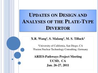
Updates on Design and Analyses of the Plate-Type Divertor. X.R. Wang 1 , S. Malang 2 , M. S. Tillack 1 1 University of California, San Diego, CA 2 Fusion Nuclear Technology Consulting, Germany ARIES-Pathways Project Meeting UCSD, CA Jan. 26-27, 2011.

E N D
Updates on Design and Analyses of the Plate-Type Divertor X.R. Wang1, S. Malang2, M. S. Tillack1 1University of California, San Diego, CA 2Fusion Nuclear Technology Consulting, Germany ARIES-Pathways Project Meeting UCSD, CA Jan. 26-27, 2011
Current Status of ARIES Finger and T-Tube Divertor Concepts • 2. HCTT(He-Cooled T-Tube)*** • Tapered ODS-steel cartridge • q”=13 MW/m2 • Pp /P th <10% • 700 ᵒC < T <1300 ᵒC for W structure • Within Elastic regime • 1. HCPF(He-cooled Combined Plate and Finger)* • q”=15 MW/m2 • Pp /P th <10% • 700 ᵒC < T <1300 ᵒC for W structure • Allowing yielding, within elastic regime after stress relaxation of plasticity **With pin-fin array, accommodating ~22 MW/m2 (without stress verification) *X.R. Wang, S. Malang and M. S. Tillack, 19th TOFE, to be published in Fusion Science and Technology. **M. Yoda, S.I. Abdel-Khalik et. all, 19th TOFE, to be published in Fusion Science and Technology. ***J. Burke and et. all, 19th TOFE, to be published in Fusion Science and Technology.
STATUS OF THE ARIES PLATE-TYPE DIVERTOR CONCEPT 3. HCFP(Helium-cooled Flat Plate) divertor Jet-to-wall distance h=1.2 mm Jet width D=0.5 mm Front plate, tf =2 mm Side wall, ts=3 mm Back plate, tb=8 mm 600 ºC Inlet One plate(front view) 2 mm He insulator gap used to makes the cooling duct operating in range of 1075-1300 °C to reduce thermal stresses ~20 cm Half of 1 m 677 ºC Outlet q”=10 MW/m2 qv=17.5 MW/m3 P=10 MPa Tin/Tout=600/677 °C HTC=~4.822x10⁴ W/m2K T thimble=1295 °C PP=9.7% Pth σ(p+s) =359 MPa(within elastic regime) One plate(Bird view) X.R. Wang, S. Malang and R. Raffray, Fusion Science and Technology, 56, 1023(2009). One Channel
CAN THE HCFP CONCEPT BE SIMPLIFIED FOR PUSHING TO HIGHER HEAT FLUX? Design Method: Allowing local yield and considering plasticity. 600 ºC Inlet Simplified to 600 ºC Inlet • Getting rid off the U-shape wall for simplifying the design • More space for increasing cross-sections for manifolds and reducing ∆P • Increasing temperature design window 7.2 cm 6 cm 677 ºC Outlet 677 ºC Outlet • Verifications needed: • CFD analyses • Elasto-plastic analysis • Cyclic thermo-mechanics 2.2 cm 2.2 cm
PARAMETER STUDIES AND OPTIMIZATIONS OF THERMAL PERFORMANCE BY USING CFX • CFX was used in the parameter studies and optimizations. • The plate without pin fins are used. • Different cooling conditions were analyzed • ∆T1=677-600 ᵒC (Original design) • ∆T2=700-623 ᵒC • ∆T3=700-600 ᵒC • Jet sizes are varying from 0.15 to 0.5 mm • The plate-type divertor can accommodate the surface heat flux up to 11 MW/m2 while staying within temperature and pumping power constraints. • Ts<~1300ᵒC (Re-crystallization temperature) • P p< ~10% P removed thermal power • The plate-type divertor with pin fins can enhance the heat transfer coefficient ( it is not included in this plot)** q’’<9 MW/m2, ∆T3 is better option q’’>9 MW/m2, ∆T1 is better option **M. Yoda, S.I. Abdel-Khalik et. all, ARIES meeting, May 2010
COMPARISON OF THERMAL PERFORMANCE FOR THREE CONCEPTS • W structure temperature limit • 700 ᵒC< Ts <1300 ᵒC • All thermal-hydraulic analyses were performed by CFX • Finger concept has better thermal performance. • The finger (HEMJ) with pin fins can handle the heat flux up to 22 MW/m2.** (it is not shown) **M. Yoda, S.I. Abdel-Khalik et. all, 19th TOFE Meeting, 2010..
Example of CFX Thermal-Fluid Results for HCFP q”=11 MW/m2 q’’’=17.5 MW/m3 P=10 MPa Tin/Tout=600/677 ᵒC Djet=0.4 mm Vjet=307 m/s Local H.T.C=7.64x10⁴ W/m2-K Pp=9.8%Premoved thermal power Max. Tarmor= 1985 ᵒC Max. Tstructure=1298 ᵒC Min. T structure=716 ᵒC Velocity distribution Temperature distribution (W-armor not shown)
Thermo-Mechanical Analysis for the Heat Flux up to 11 MW/m2 • Only half of cooling channel is considered in the thermo-mechanical simulation. • ODS insert manifold is excluded from thermo-mechanical model. • Thermal boundary conditions and structural supports: • the interface temperature of the He/W is imported from the CFX thermal results • Thermal expansion and bending are free. One coolant channel (without manifold) Temperature distribution at interface of the He/W (CFX results)
Example Results of the Elastic Structural Analysis Elastic regime 11 MW/m2 15 MW/m2 Stress distributions • The plate-type divertor can accommodate the heat flux up to 9 MW/m2 for maintaining the structure in the elastic regime (3Sm=373 MPa at Ts =1300 ᵒC).
Example of Elsto-Plastic Analyses for a Heat Flux of 11MW/m2 • Design Criteria: • Allowable plastic strain has to be less than 50% of the uniform elongation of the material: • Ɛallow=~0.8% for W at 270ᵒC • Ɛallow=~1.0% for W at 1200 ºC • The maximum plastic strains calculated by ANSYS: • Ɛpl=~0.026% in the channel • Ɛpl=~0.03% in the armor • Total deformation is ~3.1 mm (increase of the plate length) • Plastic design criteria are met for the maximum surface up to 11 MW/m2. 0.026% 0.03% Plastic strain of the cooling channel Plastic strain of the tiles (on the top of the channel)
EXAMPLE SHOWING STRESS RELAXATION FOR THE HEAT FLUX OF 11MW/M2 • SF(safety factor)=3 Sm/Combined primary and secondary stresses • SF must be >1 σmax =513 MPa, SFmin=0.73 ASME code is not met. σmax =368 MPa, SFmin=1.01 ASME code is met. Elastic-Plastic Analysis Elastic Analysis
Elasto-Plastic Analyses for the Heat Flux up to 15MW/m2 SF=1.08 SF=1.03 σp+s =424 MPa (3 Sm=~565 MPaat Ts =1000 ᵒC ) Max. Ɛ=~0.05% Max. Ɛ=~0.04% SF=1.33 • The maximum plastic strains at the channel structure and the armor ~0.04% and 0.05%, respectively (allowable plastic strain Ɛallow=~1%). • The structural behavior stays in the elastic regime after stress relaxation of the plasticity (3 Sm=~410 MPa at Ts =1265 ᵒC). However, the pumping power for the heat flux of 15 MW/m2 is too high and the minimum temperature < 700 ᵒC.
Summary and Conclusions • The HCFP divertor has been re-investigated and simplified by considering “yielding”, stress-relaxation and plasticity, and the U-tube for stagnant helium insulator gap inside of channel can be eliminated. • Parametric studies have been performed by 3D CFX, and thermal-hydraulic results indicate that: • ∆T3=Texit-Tinlet=700-600 ᵒC is better option for the q”<9 MW/m2 • ∆T1=Texit-Tinlet=677-600 ᵒC is better option for the q”>9 MW/m2 • The simplified HCFP divertor can accommodate the surface heat flux up to 11 MW/m2 while staying into the temperature and pumping power limits. • Stress is not very important limit constraint any more comparing to the temperature and pumping power when the local yielding is allowed. • However, it remains to be seen if cyclic loading leads to ratcheting with ƐPl>Ɛ allow. • Modifications for all the divertor concepts are required to increase minimum W temperature from ~720 ᵒC to >800 ᵒC.