RUBE GOLDBERG
330 likes | 776 Vues
RUBE GOLDBERG. Mr.Masters CADD. WHO IS RUBE GOLDBERG?. 1) Discuss who Rube Goldberg is and what he did. Talk about his machines. . A fun example of a Rube Goldberg machine : http:// www.youtube.com / watch?v =qybUFnY7Y8w And here is one done by MythBuster’s :

RUBE GOLDBERG
E N D
Presentation Transcript
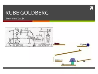
RUBE GOLDBERG Mr.Masters CADD
WHO IS RUBE GOLDBERG? • 1) Discuss who Rube Goldberg is and what he did. Talk about his machines.
A fun example of a Rube Goldberg machine: http://www.youtube.com/watch?v=qybUFnY7Y8w And here is one done by MythBuster’s: http://www.youtube.com/watch?v=lCYg_gz4fDo&feature=related VIDEOS Youtube
YOUR JOB RANDOM TRASH AT HOME
DESGIN PROCESS • In the process of inventing, there are several steps regardless of the machine. 1. Determine what needs to be accomplished (What is the problem? Who is the device for?). 2. What are the constraints, materials, time allotted, safety, etc? Meet the given specifications. 3. Brainstorm! What simple machines can you use? Write and draw your ideas to save time and materials! 4. Make sure your ideas meet the design requirements. Materials lists are a good idea. 5. Once all the steps above are met, build! Try to utilize materials. 6. Test and troubleshoot! 7. Rebuild!
Objectives • 1) Understand the basic ideas of machines and mechanical advantages. • 2) Understand the Engineering Design Process. 3) Learn to troubleshoot.
MECHANICAL ADVANTAGE • Mechanical Advantage – The number of times a force exerted on a machine is multiplied by the machine (mechanical advantage = output/input). • ○ Simple Machines – Machines that make work easier for people. • ○ Compound Machine – Two or more simple machines combined together to make one unit or machine to further simplify work.
SIMPLE MACHINE • Requirements: Draw a “Rube Goldberg”-style machine that uses at least 5 different types of simple machines to accomplish one task. • Types of simple machines: levers, pulleys, inclined planes, screws, wedges, and wheel and axles. • • You must use at least 5 different types of simple machines, but may use as many of each as needed. (For example, you may use 3 levers, 2 pulleys, and 1 inclined plane.)
WHEEL AND AXLE • Wheel and Axle • In this machine a wheel or spoke is locked to a central axle so that when one is turned the other must turn. A longer motion at the edge of the wheel is converted to a shorter more powerful motion at the axle. In reverse, a short powerful force at the axle will move the wheel's edge a greater distance.
PULLEY SYSTEM • Pulley System • A single pulley simply reverses the direction of a force. When two or more pulleys are connected together, they permit a heavy load to be lifted with less force. The trade-off is that the end of the rope must move a greater distance than the load.
WEDGE • Wedge • A wedge converts motion in one direction into a splitting motion that acts at right angles to the blade. Nearly all cutting machines use the wedge. A lifting machine may use a wedge to get under a load.
SCREW • Screw • A screw is a central core with a thread or groove wrapped around it to form a helix. While turning, a screw converts a rotary motion into a forward or backward motion.
GEARS • Gears • Gears are toothed or pegged wheels meshed together to transmit motion and force. In any pair of gears the larger one will rotate more slowly than the smaller one, but will rotate with greater force. Each gear in a series reverses the direction of rotation of the previous gear.
BEVEL GEARS • Bevel Gears • Gears that mesh at an angle change the direction of rotation.
WORM GEAR • Worm Gear • A worm gear is a combination of a gear meshed with the threads of a screw. This combination changes the direction of turning motion by ninety degrees. Worm gears also decrease the speed of turning from screw to gear and increase its force.
RACK AND PINION • Rack and Pinion • A single gear, the pinion, meshes with a sliding toothed rack. This combination converts rotary motion to back and forth motion. Windshield wipers in cars are powered by a rack and pinion mechanism. A small pinion at the base of the wiper meshes with a sliding rack below.
CRANK AND ROD • Crank and Rod • The crank is a wheel with a pivoting arm attached near its edge. The arm is attached by a hinge to a rod. When the crank turns, the rod is pushed back and forth. Alternatively, if the rod is pushed back and forth at the right speed, the crank will turn. The crank and rod shown here are part of giant steam engine
CHAINS AND BELTS • Chains and Belts • A chain or belt connects two separated wheels so that one turns, the other will turn in the same direction.
RATCHET • Ratchet • A ratchet is a device that allows a wheel to turn in only one direction. The ratchet wheel has specially shaped teeth. A bar on a pivot called the "pawl" is fixed above the ratchet wheel. The pawl slides over the teeth of the ratchet in one direction, but blocks the motion of the teeth if the wheel turns in the other direction.
MACHINE OPERATION • Explanation of Machine: • Step • Explanation • 1. Windup robot toy is released. Toy moves rightward across platform, knocking the ball off the platform. • 2. The ball rolls off of the platform and falls into cup A. This upsets the balance of the Atwood Machine, causing cup A to accelerate downward while cup B accelerates upward.
GRADE LAYOUT • 1. Participation 15pts (wk1) 15pts (wk2) 30 points • 2. Sketch 20 points • 3. Machine Operation (Typed) 10 points • 4. Team work in groups 10 points • 5. Project 30 points • Total points 100 points