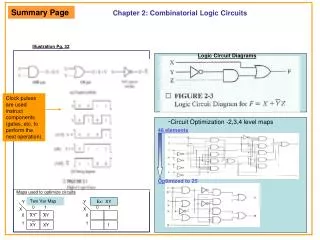
Chapter 3 – Describing Logic Circuits
Chapter 3 – Describing Logic Circuits. Chapter 3 Objectives. Selected areas covered in this chapter : Operation of truth tables for AND , NAND , OR , and NOR gates, and the NOT (INVERTER) circuit. Boolean expression for logic gates. DeMorgan’s theorems to simplify logic expressions.


Chapter 3 – Describing Logic Circuits
E N D
Presentation Transcript
Chapter 3 Objectives • Selected areas covered in this chapter: • Operation of truth tables for AND, NAND, OR, and NOR gates, and the NOT (INVERTER) circuit. • Boolean expression for logic gates. • DeMorgan’s theorems to simplify logic expressions. • Universal gates (NAND or NOR) to implement a circuit represented by a Boolean expression. • Concepts of active-LOW & active-HIGH logic signals. • Describing and measuring propagation delay time. • Differences between an HDL and a computer programming language.
3-1 Boolean Constants and Variables • Boolean algebra allows only two values—0 and 1. • Logic 0 can be: false, off, low, no, open switch. • Logic 1 can be: true, on, high, yes, closed switch. • The three basic logic operations: • OR, AND, and NOT.
3-2 Truth Tables • A truth table describes the relationship between the input and output of a logic circuit. • The number of entries corresponds to the number of inputs. • A 2-input table would have 22 = 4 entries. • A 3-input table would have 23 = 8 entries.
Examples of truth tables with 2, 3, and 4 inputs. 3-2 Truth Tables
The + sign does not stand for ordinaryaddition—it stands for the OR operation In the Boolean expression x = 1 + 1 + 1 = 1… x is true (1) when A is true (1) OR B is true (1) OR C is true (1) 3-3 OR Operation With OR Gates • The Boolean expression for the OR operation is: X = A + B — Read as “X equals AOR B” • The OR operation is similar to addition, but when A = 1 and B = 1, the OR operation produces: 1 + 1 = 1 not 1 + 1 = 2
Truth table/circuit symbol for a two input OR gate. 3-3 OR Operation With OR Gates • An OR gate is a circuit with two or more inputs, whose output is equal to the OR combinationof the inputs.
Truth table/circuit symbol for a three input OR gate. 3-3 OR Operation With OR Gates • An OR gate is a circuit with two or more inputs, whose output is equal to the OR combinationof the inputs.
3-3 OR Operation With OR Gates Example of the use of an ORgate in an alarm system.
The + sign does not stand for ordinarymultiplication—it stands for the AND operation. x is true (1) when A AND B AND C are true (1) Truth table — Gate symbol. 3-4 AND Operations with AND gates • The AND operation is similar to multiplication: X = A • B • C— Read as “X equals AAND B AND C”
Truth table/circuit symbol for a three input AND gate. 3-4 AND Operations with AND gates
AND / OR The AND symbol on a logic-circuit diagram tells you output will go HIGH onlywhen all inputs are HIGH. The OR symbol means the output will go HIGH whenany input is HIGH.
The overbar representsthe NOT operation. Another indicator for inversion is theprime symbol ('). A' = A X = A NOT Truth Table 3-5 NOT Operation • The Boolean expression for the NOT operation: — Read as: “X equals NOTA” “X equals the inverse of A” “X equals the complement of A”
A NOT circuit—commonly called an INVERTER. This circuit always has only a single input, and the out-putlogic level is always opposite to the logic level of this input. 3-5 NOT Operation
Whenever the input = 0, output = 1, and vice versa. 3-5 NOT Operation The INVERTER inverts (complements) theinput signal at all points on the waveform.
This circuit provides an expression that is true when the button is not pressed. 3-5 NOT Operation Typical application of the NOT gate.
These three basic Boolean operationscan describe any logic circuit. Boolean Operations Summarized rules for OR, AND and NOT
3-6 Describing Logic Circuits Algebraically • If an expression contains both AND and OR gates, the AND operation will be performed first. • Unless there is a parenthesis in the expression.
Whenever an INVERTER is present, output is equivalent to input, with a bar over it. • Input A through an inverter equals A. 3-6 Describing Logic Circuits Algebraically
3-6 Describing Logic Circuits Algebraically • Further examples…
3-6 Describing Logic Circuits Algebraically • Further examples…
3-7 Evaluating Logic Circuit Outputs • Rules for evaluating a Boolean expression: • Perform all inversions of single terms. • Perform all operations within parenthesis. • Perform AND operation before an OR operation unless parenthesis indicate otherwise. • If an expression has a bar over it, perform operations inside the expression, and then invert the result.
3-7 Evaluating Logic Circuit Outputs • The best way to analyze a circuit made up of multiple logic gates is to use a truth table. • It allows you to analyze one gate or logiccombination at a time. • It allows you to easily double-check your work. • When you are done, you have a table of tremendous benefit in troubleshooting the logic circuit.
Node u has been filled as the complement of A 3-7 Evaluating Logic Circuit Outputs • The first step after listing all input combinationsis to create a column in the truth table for each intermediate signal (node).
v =AB — Node v should be HIGHwhen A (node u) is HIGH ANDB is HIGH 3-7 Evaluating Logic Circuit Outputs • The next step is to fill in the values for column v.
This column is HIGH whenever B is HIGH ANDC is HIGH 3-7 Evaluating Logic Circuit Outputs • The third step is to predict the values at node w which is the logical product of BC.
Since x = v + w, the x output will be HIGH when v ORw is HIGH 3-7 Evaluating Logic Circuit Outputs • The final step is to logically combine columns v and w to predict the output x.
3-7 Evaluating Logic Circuit Outputs • Output logic levels can be determined directly from a circuit diagram. • Output of each gate is noted until final output is found. • Technicians frequently use this method.
3-7 Evaluating Logic Circuit Outputs Table of logic stateat each node of thecircuit shown.
A circuit defined by X = A + B, would use a two-input OR gate with an INVERTER on one ofthe inputs. 3-8 Implementing Circuits From Boolean Expressions • It is important to be able to draw a logic circuit from a Boolean expression. • The expression X = A • B • C, could be drawnas a three input AND gate.
A circuit with output y = AC + BC + ABCcontains three terms which are ORed together. …and requires a three-input OR gate. 3-8 Implementing Circuits From Boolean Expressions
3-8 Implementing Circuits From Boolean Expressions • Each OR gate input is an AND product term, • An AND gate with appropriate inputs can beused to generate each of these terms.
Circuit diagram to implement x = (A + B)(B + C) 3-8 Implementing Circuits From Boolean Expressions
3-9 NOR Gates and NAND Gates • Combine basic AND, OR,and NOT operations. • Simplifying the writing of Boolean expressions • Output of NAND and NOR gates may be foundby determining the output of an AND or ORgate, and inverting it. • The truth tables for NOR and NAND gates show the complement of truth tables for OR and AND gates.
An inversion “bubble” is placed at the outputof the OR gate, making the Boolean output expression x = A + B 3-9 NOR Gates and NAND Gates • The NOR gate is an inverted OR gate.
3-9 NOR Gates and NAND Gates Output waveform of a NOR gate forthe input waveforms shown here.
The NAND gate is an inverted AND gate. • An inversion “bubble” is placed at the outputof the AND gate, making the Boolean outputexpression x = AB 3-9 NOR Gates and NAND Gates
3-9 NOR Gates and NAND Gates Output waveform of a NAND gate forthe input waveforms shown here.
Logic circuit with the expression x = AB •(C + D)using only NOR and NAND gates. 3-9 NOR Gates and NAND Gates
3-10 Boolean Theorems The theorems or laws that follow may represent an expression containing more than one variable.
Theorem (1) states that if any variableis ANDed with 0, the result must be 0. Theorem (2) is also obviousby comparison with ordinarymultiplication. Prove Theorem (3) by trying each case.If x = 0, then 0 • 0 = 0 If x = 1, then 1 • 1 = 1 Thus, x •x = x Theorem (4) can be provedin the same manner. 3-10 Boolean Theorems
Theorem (5) is straightforward,as 0 added to anything does not affect value, either in regular addition or in OR addition. Theorem (6) states that if any variableis ORed with 1, the is always 1. Check values: 0 + 1 = 1 and 1 + 1 = 1. Theorem (7) can be proved bychecking for both values of x:0 + 0 = 0 and 1 + 1 = 1. Theorem (8) can be proved similarly. 3-10 Boolean Theorems
Commutative laws Associative laws Distributive law 3-10 Boolean Theorems Multivariable Theorems
Analysis table & factoringfor Theorem (14) 3-10 Boolean Theorems Multivariable Theorems Theorems (14) and (15) do not have counterpartsin ordinary algebra. Each can be proved bytrying all possible cases for x and y.
Theorem (16) says inverting the OR sum of two variables is the same as inverting each variable individually, then ANDing the inverted variables. Theorem (17) says inverting the AND product of two variables is thesame as inverting each variable individually and then ORing them. Each of DeMorgan’s theorems can readily be proven by checking for all possible combinations of x and y. 3-11 DeMorgan’s Theorems • DeMorgan’s theorems are extremely useful in simplifying expressions in which a product orsum of variables is inverted.
Equivalent circuits implied by Theorem (16) The alternative symbolfor the NOR function. 3-11 DeMorgan’s Theorems
Equivalent circuits implied by Theorem (17) The alternative symbolfor the NAND function. 3-11 DeMorgan’s Theorems
3-12 Universality of NAND and NOR Gates • NAND or NOR gates can be used to create the three basic logic expressions. • OR, AND, and INVERT. • Provides flexibility—very useful in logic circuit design.
It is possible, however, to implement any logic expression using only NAND gates and no other type of gate, as shown. 3-12 Universality of NAND and NOR Gates How combinations of NANDs or NORs areused to create the three logic functions.