Download
1 / 19
290 likes | 587 Vues
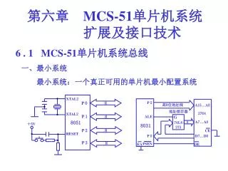
8051 Interrupts & Timers. Abdul Qadir Javaid E204 abdulqadir_17@hotmail.com abdul.q.javaid@theiet.org. Diagram taken from ‘The 8051 Microcontroller Architecture, Programming & Applications’ by Kenneth J. Ayala. Interrupts.

E N D
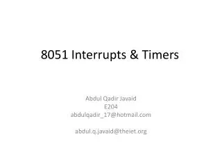
8051 Interrupts & Timers Abdul Qadir Javaid E204 abdulqadir_17@hotmail.com abdul.q.javaid@theiet.org
Diagram taken from ‘The 8051 Microcontroller Architecture, Programming & Applications’ by Kenneth J. Ayala
Interrupts • Two ways to make the computer program make aware of the internal and external conditions of the circuit • Software instructions and the hardware signals • 5 interrupts in 8051 • 3 internal interrupts: timer flag 0, timer flag1 & Serial port interrupt • 2 external at pins INT0 & INT1
Timer flag interrupt: The timer/counter overflow flag TF0 & TF1 is set to 1. • Serial Port interrupt • External interrupt: INT0 & INT1. • 2 ways to set the interrupt flags IE0 & IE1 in TCON to 1.
Interrupt Registers Bit Symbol Function 7 EA Enable Interrupt bit. If logic 0 clears the interrupts. Set to 1 enables. 6 -- Not implemented. 5 ET2 Reserved for future use. 4 ES Enable Serial port. If 1 then enables. If 0 then disables. 3 ET1 Enable timer 1 overflow. If 1 then enables. If 0 then disables. 2 EX1 Enable external interrupt 1 if set to 1 to enable INT1 1 ET0 Enable timer 0 overflow if set to 1. 0 EX0 Enable external interrupt 0 if set to 1 to enable INT0
Bit Symbol Function • 7 -- Not implemented • 6 -- Not implemented • PT2 Set for future use • 4 PS Priority for Serial port interrupt. • Set or cleared by programmer. • 3 PT1 Priority of timer 1 overflow interrupt • 2 PX1 Priority of external interrupt • 1 PT0 Priority of timer 0 overflow interrupt • 0 PX0 Priority of external interrupt 0
Interrupt causes a hardware call to one of the memory locations Programmer should place a service routine at that address Interrupt saves the PC of the program on the stack
Oscillator ‘f’ is smallest interval of time 1 instruction takes 1 machine cycle 12MHz crystal 1msec for one instruction
Bit 7/5(TF1/TF0): Timer1/0 overflow flag. Set when timer rolls from all ones to zeros. Cleared when processor executes the interrupt routine.Bit 6/4(TR1/TR0): Timer1/0 run control bit. Set to one to enable timer to count. Cleared to zero to stop. Does not reset.Bit 3/1(IE1/IE0): External Interrupt 1/0 Edge flag. Set to 1 when high-low signal at port 3.3(INT1) & port 3.2(INT0). Cleared by interrupt service routine. Bit 2/0(IT1/IT0): External Interrupt 1/0 type control bit. TCON Register
Bit 7/3 (Gate) : OR gate enable bit. Controls RUN/STOP of timer 1/0. If TRx = 1, Gate = 1, timer runs when INT is high.If Gate = 0, timer runs when TRx = 1.Bit 6/2 (C/T) : Set to 1 for timer 1/0 to act as Counters for external input pulses at pins 3.5(T1) or 3.4(T0). Set to 0 for timer.Bit 5/1 (M1) : Timer/Counter Operating mode select bit 1.Bit 4/0 (M0) : Timer/Counter Operating mode select bit 0. Not Bit Addressable
TIMER MODE 0 • THX as 8-bit counter • TLX as 5-bit counter
TIMER MODE 1 • Similar to Mode 0 • Behaves as a 16 bit timer • E-g If its required for timer to overflow after 1000 counts then load FCh in THX and 18h in TLX. • 16 bit counter max value is (65535) • If 6MHz crystal used then timer flag sets in 0.1311 sec
TIMER MODE 2 • Only TLX used as counter • THX to hold a value • Auto-reload mode • TLX counts up from number in THX • Overflows & Initialised to the number in THX
TIMER MODE 3 • So far Timer 0 and Timer 1 has been shown to be behaving independently • Not true for Mode 3 • If mode 3 chosen for timer 0, then placing timer1 in mode 3 causes it to stop counting • TR1 & TF1 used by timer 0 • Timer 0 becomes 2 separate 8-bit counters
Contd.... • TL0 overflows(00h-FFh) & sets timer flag TF0 • TH0 behaves under the control of TR1 & sets TF1 when overflows • If timer 0 in mode 3: Timer 1 can be used in mode 0, 1 & 2 with 1 exception: No interrupts will be generated • Timer1 can be used for baud rate generation of serial port
Difference between Timer & Counter • Source of clock pulses • Timer : Clock pulses from oscillator • Counter: Pin T0(P3.4) for counter 0 Pin T1(P3.5) for counter 1 C/T bit must be set for counter • Maximum input frequency is Oscillator frequency/24
Example START Turn off the LED IF push button is On THEN Initialize timer 1 to genrate interrupts Wait for timer interrupt ENDIF END Timer 1 initialization START Enable timer 1 interrupts Set timer 1 to 8-bit auto reload mode Load timer value Enable microcontroller interrupts Turn on timer 1 END Timer 1 Interrupt service routine START IF the required time has elapsed THEN Turn LED on or off ENDIF END
CODE #include<reg51.h> sbit LED = P1^7; sbitpush_button = P3^2; int count; void init_timer(); /*Main Program*/ main() { count = 0; //Initialize count LED = 1; //LED is OFF while(push_button == 1) //Scan for the push button { } init_timer(); //Initialize timer1 for(;;) //Endless loop { } } //End of main program /*Timer 1 Initialization routine*/ void init_timer() { ET1=1 ; //Enable timer 1 TMOD = 0x20; //Timer 1 in mode 2 TH1 = 0x6; //For 250msec pulse EA = 1; //Enable interrupts TR1 = 1; //Turn on timer 1 }
Contd... /*Timer 1 interrupt service routine*/ timer1() interrupt 3 { count++; //increment count if(count ==100) { count = 0; //Reset count LED = ~LED; } }