Download
1 / 24
240 likes | 426 Vues
History of Computers. Generations. 0) Mechanical computers (1642 1945) 1) Vacuum tube (1946 1957) 2) Transistor (1958 1964) 3) Integrated circuit (IC) (1965 1971) Small- and medium-scale (SSI, MSI) 10’s to 100’s of transistors 4) IC, LSI (1972 1977); 10’s of thousands

E N D
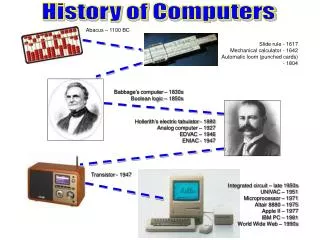
Generations • 0) Mechanical computers (1642 1945) • 1) Vacuum tube (1946 1957) • 2) Transistor (1958 1964) • 3) Integrated circuit (IC) (1965 1971) • Small- and medium-scale (SSI, MSI) • 10’s to 100’s of transistors • 4) IC, LSI (1972 1977); 10’s of thousands • 5) IC, VLSI (1978 ); over 100,000
0th Gen: Mechanical • Blaise Pascal • Age 19 • Gears and crank • Addition and subtraction • Wilhelm von Leibniz • Multiplication and division too • Charles Babbage • Analytical Engine • 4 components: memory, computation unit, input, output • First general purpose programmable machine • First programmer: Ada Lovelace • Buggy
1st Gen: Vacuum Tubes • Electronic Numerical Integrator And Computer (ENIAC) • Mauchly and Eckert at U Penn • First GP electronic computer digital computer • Contracted by Army’s Ballistics Research Laboratory for WWII • Finished too late for war
1st Gen: Vacuum Tubes • ENIAC • Trajectory tables first, then feasibility of hydrogen bomb • 80 feet long by 8.5 feet high and several feet wide • Twenty 10 digit registers, each 2 feet long • ~18,000 vacuum tubes • ~5,000 additions/second • 30 tons • 100 kHz clock
1st Gen: Vacuum Tubes • IAS • Princeton’s Institute for Advanced Studies • John von Neumann (consultant ENIAC project) • Stored-program concept • Store program in memory along with data • About same time by Alan Turing • Prototype for all subsequent GP computers
Proposal for IAS Quote from von Neumann’s proposal [VONN45]: 2.2 First: Because the device is primarily a computer, it will have to perform the elementary operations of arithmetic most frequently. These are addition, subtraction, multiplication and division. It is therefore reasonable that it should contain specialized organs for just these operations. It must be observed, however, that while this principle as such is probably sound, the specific way in which it is realized requires close scrutiny. At any rate a central arithmetical part of the device will probably have to exist and this constitutes the first specific part: CA. 2.3 Second: The logical control of the device, that is, the proper sequencing of its operations, can be most efficiently carried out by a central control organ. If the device is to be elastic, that is, as nearly as possible all purpose, then a distinction must be made between the specific instructions given for and defining a particular problem, and the general control organs which see to it that these instructions—no matter what they are—are carried out. The former must be stored in some way; the latter are represented by definite operating parts of the device. By the central control we mean this latter function only, and the organs which perform it form the second specific part: CC.
Proposal for IAS 2.4 Third: Any device which is to carry out long and complicated sequences of operations (specifically of calculations) must have a considerable memory . . . (b) The instructions which govern a complicated problem may constitute considerable material, particularly so, if the code is circumstantial (which it is in most arrangements). This material must be remembered. At any rate, the total memory constitutes the third specific part of the device: M. 2.6 The three specific parts CA, CC (together C), and M correspond to the associative neurons in the human nervous system. It remains to discuss the equivalents of the sensory or afferent and the motor or efferent neurons. These are the input and output organs of the device. The device must be endowed with the ability to maintain input and output (sensory and motor) contact with some specific medium of this type. The medium will be called the outside recording medium of the device: R.
Proposal for IAS 2.7Fourth: The device must have organs to transfer . . . information from R into its specific parts C and M. These organs form its input, the fourth specific part: I. It will be seen that it is best to make all transfers from R (by I) into M and never directly from C. 2.8 Fifth: The device must have organs to transfer . . . from its specific parts C and M into R. These organs form its output, the fifth specific part: O. It will be seen that it is again best to make all transfers from M (by O) into R, and never directly from C.
The Organization of IAS Computer Accumulator (AC) Multiplier/Quotient (MQ) Input/ Output Equipment Arithmetic Logic Circuits DATAPATH Memory Buffer Register (MBR) Input Buffer (IBR) Program Counter (PC) Main Memory (M) 100040 bit words Instruction Register (IR) Memory Address Reg. (MAR) Control Circuits Control Signals CONTROL UNIT
IAS Computer Machine Language 40-bit word, two machine instructions per word. Left instruction Right instruction bit 0 7 8 19 20 27 28 39 8-bit opcode 12-bit memory address (operand)
IAS Data Transfer Instructions (7) Instruction Opcode Description LOAD MQ 00001010 AC ← MQ LOAD MQ, M(X) 00001001 MQ ← M(X) STOR M(X) 00100001 M(X) ← AC LOAD M(X) 00000001 AC ← M(X) LOAD – M(X) 00000010 AC ← – M(X) LOAD |M(X)| 00000011 AC ← |M(X)| LOAD – |M(X)| 00000100 AC ← – |M(X)|
IAS Unconditional Branch Instructions (2) Instruction Opcode Description JUMP M(X,0:19) 00001101 next instruction from M(X,0:19) JUMP M(X,20:39) 00001110 next instruction from M(X,20:39)
IAS Conditional Branch Instructions (2) Instruction Opcode Description JUMP +M(X,0:19) 00001111 IF AC≥0, then next instr. from M(X,0:19) JUMP +M(X,20:39) 00001110 IF AC≥0, then next instr. M(X,20:39)
IAS Arithmetic Instructions (8) Instruction Opcode Description ADD M(X) 00000101 AC ← AC + M(X) ADD |M(X)| 00000111 AC ← AC + |M(X)| SUB M(X) 00000110 AC ← AC ─ M(X) SUB |M(X)| 00001000 AC ← AC ─ |M(X)| MUL M(X) 00001011 AC, MQ ← MQ × M(X) DIV M(X) 00001100 MQ, AC ← MQ / M(X) LSH 00010100 AC ← AC x 2 RSH 00010101 AC ← AC / 2
IAS Address Modify Instructions (2) Instruction Opcode Description STOR M(X,8:19) 00010010 M(X,8:19) ← AC(28:39) STOR M(X,28:39) 00010011 M(X,28:39) ← AC(28:39)
How IAS Computer Adds Two Numbers • Suppose numbers are stored in memory locations 100 and 101, and • Sum is to be saved in memory location 102 Instruction Opcode Description LOAD M(100) 00000001 AC ← M(100) ADD M(101) 00000101 AC ← AC + M(101) STOR M(102) 00100001 M(102) ← AC
IAS Computer Machine Code 00000001 000001100100 00000101 000001100101 Load 100 Add 101 00100001 000001100110 00000000 000000000000 Stor 102
Save Program in Memory Address 0 First program word Second program word Address Memory Load PC Word 100 Word 101 Word 102 Address max
Executing the Program Accumulator (AC) Multiplier/Quotient (MQ) Input/ Output Equipment Arithmetic Logic Circuits DATAPATH Memory Buffer Register (MBR) Input Buffer (IBR) Program Counter (PC) Main Memory (M) 100040 bit words Instruction Register (IR) Memory Address Reg. (MAR) Control Circuits Control Signals CONTROL UNIT
IAS Instruction Cycles • Store machine code in contiguous words of memory • Place the starting address in PC • Start program: MAR ← PC • Read memory: IBR ← MBR ← M(MAR), fetch cycle • Place left instruction in IR and address 100 in MAR
IAS Instruction Cycles • Read memory: AC ← M(100), fetch cycle • Place right instruction in IR and address 101 in MAR • Read memory and add: AC ← AC + M(101), execution cycle • PC ← PC + 1
IAS Instruction Cycles (Cont.) • MAR ← PC • Read memory: IBR ← MBR ← M(MAR), fetch cycle • Place left instruction in IR and address 102 in MAR • MBR ← AC • Write memory