LC Voltage Control Oscillator AAC
280 likes | 300 Vues
Explore a stable negative feedback loop for LC voltage-controlled oscillators (VCOs) to regulate oscillation amplitudes. Learn about loss-control feedback loops and Q-tuning techniques. Detailed explanations and experimental results provided.

LC Voltage Control Oscillator AAC
E N D
Presentation Transcript
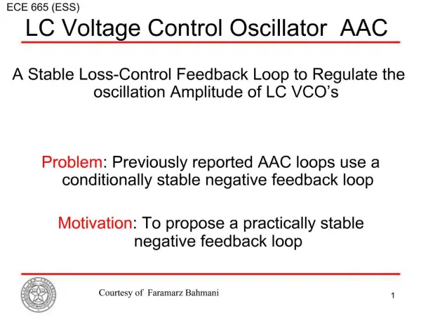
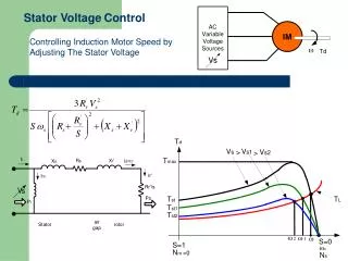
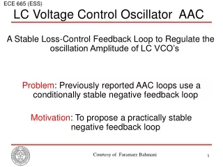
ECE 665 (ESS) LC Voltage Control Oscillator AAC A Stable Loss-Control Feedback Loop to Regulate the oscillation Amplitude of LC VCO’s Problem: Previously reported AAC loops use a conditionally stable negative feedback loop Motivation: To propose a practically stable negative feedback loop Courtesy of Faramarz Bahmani
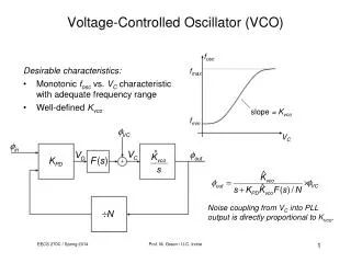
VCO Amplitude Control • More on VCO AAC loop • Fast and reliable start up. • Optimal bias point in terms of phase noise performance. • Adequate amplitude over wide oscillation frequency range. • Variations of oscillation amplitude could be fast when other digital blocks pull the ground or the power supply rails. • VCO-based Q-tuning. Courtesy of Faramarz Bahmani
ECE 665 (ESS LC Filters • Active LC filters The advent of highly integrated wireless communication transceivers. Persistent effort to improve the quality of on-chip spiral inductors. Superior dynamic range performance. However, Reactive elements integrated on silicon are more non-ideal than corresponding discrete parts. Automatic tuning is a major challenge. Courtesy of Faramarz Bahmani
LC Filters: Q-Tuning • Tuning techniques • Direct tuning: Self-tuning • Filter is the plant in the tuning system • Tuning accuracy doesn’t rely on matching. • Indirect tuning: master-slave • VCF-based : Master is a filter • VCO-based : Master is a VCO Courtesy of Faramarz Bahmani
LC Filters: Q-Tuning • VCF-base tuning • A reference signal with low harmonic content. • A phase detector having low offsets. • Since output amplitude varies with frequency thus Q-tuning loop heavily relies on frequency tuning loop. • VCO-base tuning • No reference signal is needed. • Amplitude and phase of the VCO are independent, theoretically, thus the Q-tuning and frequency tuning loops are not affecting each other. • Leakage of the VCO output to signal path. • Inherent nonlinearity of VCO and its effect on Q-tuning accuracy. Courtesy of Faramarz Bahmani
VCO-Based Q-Tuning • Principle of Operation • VCO: Large signal Courtesy of Faramarz Bahmani
VCO-Based Q-Tuning Courtesy of Faramarz Bahmani
VCO-Based Q-Tuning • Experimental results Q=50, 75, 115, 160 3- F. Bahmani, E. Sanchez-Sinencio, ”VCO-based quality factor tuning of a second-order LC filter at 2.25GHz” Under revision of IEE Electronics Letters, 2006. Courtesy of Faramarz Bahmani
Loss-Control Feedback Courtesy of Faramarz Bahmani
Loss-Control Feedback Courtesy of Faramarz Bahmani
Loss-Control Feedback • Control the overall LC tank’s loss by changing Gneg • Different signs of the denominator: unstable! Courtesy of Faramarz Bahmani
How can we stabilize the LCF loop? • Use a local feedback loop (F) Courtesy of Faramarz Bahmani
Transient Behavior of the Proposed LCF • Step Response • Trade-off between power and settling time Courtesy of Faramarz Bahmani
Loss-Control Feedback: Implementation • Experimental results Courtesy of Faramarz Bahmani
Loss-Control Feedback: Experimental Results • Phase noise F=2 Stable F=0 Unstable Courtesy of Faramarz Bahmani
Loss-Control Feedback: Experimental Results • Stability over the amplitude tuning range Measured oscillation amplitude (■) Phase noise (●) HD3 (▲) 4- F. Bahmani, E. Sanchez-Sinencio,”A stable loss-control feedback Loop for amplitude regulation of LC Oscillators” IEEE Transactions on Circuit and Systems I, 2006. Courtesy of Faramarz Bahmani
A New Q-Tuning Scheme: Why? • To tune the quality factor of an LC filter • VCO-based approach is the best choice • Needs perfect match between the LC filter and LC VCO • Needs a stable amplitude control loop for VCO • The tuning range of Q depends on the VCO amplitude and nonlinearities of the Gneg: • Is there any way to tune Q to an arbitrary value? Courtesy of Faramarz Bahmani
LC Filters Q-Tuning An Accurate Automatic Quality Factor Tuning Scheme for Gigahertz Range LC Filters Courtesy of Faramarz Bahmani
LC Filters Q-Tuning • Basics of 2nd order LC filter Courtesy of Faramarz Bahmani
LC Filters Q-Tuning • Basics idea: • Two amplitude locked loop: one at ω0 and the other one at ωL. Courtesy of Faramarz Bahmani
LC Filters Q-Tuning • Proposed Scheme Courtesy of Faramarz Bahmani
LC Filters Q-Tuning • Stability analysis via phase portrait technique Courtesy of Faramarz Bahmani
LC Filters Q-Tuning: Implementation • One filter is used to overcome the mismatch problem Courtesy of Faramarz Bahmani
LC Filters Q-Tuning: Multiplier • Self-multiplier • Linearized Gilbert cell Courtesy of Faramarz Bahmani
LC Filters Q-Tuning: Experimental Results • Independent tuning of Q and A0 A0(dB)={-15, -10, -5, 0} Q={60, 80, 120, 220} Q={50, 60, 70, 120} A0(dB)=0. 5- F. Bahmani, T. S. Gotarredona, E. Sanchez-Sinencio, ”An accurate quality factor and amplitude tuning scheme for high frequency LC bandpass filters ” submitted to the IEEE Transaction on Circuit and System I, 2006. Courtesy of Faramarz Bahmani
Conclusion • A stable amplitude control feedback loop for LC VCO’s is proposed and its application in the VCO-based Q-tuning of LC filters are demonstrated • An accurate Q-tuning scheme for 2nd order active LC filters is presented. Courtesy of Faramarz Bahmani
References • F. Bahmani, and E. Sánchez-Sinencio, "A Stable Loss Control Feedback Loop for VCO Amplitude Tuning", IEEE Transaction on Circuits and Systems I: Regular Papers: Volume: 53, Issue 12, pp. 2498-2506, Dec. 2006. • F. Bahmani, E. Sánchez-Sinencio, ”VCO-based quality factor tuning of a second-order LC filter at 2.25GHz” in dissertation • F.Bahmani, T. Serrano-Gotarredona, and E. Sánchez-Sinencio, "An Accurate Automatic Quality Factor Tuning Scheme for 2nd-Order LC Filters", IEEE Transaction on Circuits and Systems I, pp745-756, Vol 54, Issue 4, April 2007. Courtesy of Faramarz Bahmani
Publication • F. Bahmani, E. Sanchez-Sinencio, ”A Low THD, 10.7 MHz Tuned Oscillator Using Positive Feedback And Multilevel Hard Limiter” submitted to the IEE Transaction on Circuits, Devices and Systems, 2006. • F. Bahmani, E. Sanchez-Sinencio, ”A highly Linear 3rd order CMOS Pseudo-Differential Low Pass Filter” to be submitted to the Journal of Solid State Circuit, 2006. • S. W. Park, F. Bahmani, E. Sanchez-Sinencio, ”A 10.7 MHz Linearized Switched-Capacitor Based Oscillator Using the Multilevel Hard Limiter” To be submitted to the IEEE Journal of Solid State Circuit, 2006. Courtesy of Faramarz Bahmani