Download
1 / 68
720 likes | 791 Vues
This guide covers the fundamentals of magnetism, inductor basics, core geometries, and practical considerations. Learn about the operation and uses of inductors, as well as how core shapes affect performance. Discover the different types of magnetic components and their applications in real-world scenarios. Gain insights into the hysteresis loop, gaps in cores, and the significance of magnetic forces in electronic systems.

E N D
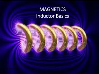
MAGNETICS Inductor Basics www.murata-ps.com Confidential
Magnetics Basics • AGENDA • Magnetism – What is it? • Common Magnetic Components • Inductor Basics • Inductor Geometries • Basic Equations of Operation • Uses of Inductors • Practical Applications & Limitations • The Hysteresis Loop • Gaps – Why and How?
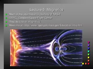
Magnetics Basics WHAT IS MAGNETISM? “Relativistic correction to electrostatic forces between moving charges”
Magnetics Basics School Basics r − + F Charge Q1 Charge Q2 Coulomb’s law
Magnetics Basics School Basics r F Charge Q1 Charge Q2 Coulomb’s law
Magnetics Basics • Charge on the electron (basic unit of charge) is: • −1.602176565 ×10⁻¹⁹ Coulombs • This is a derived number, 1C being defined as the amount of charge moved in 1s at a current of 1A • Never been known to vary under any condition, static or moving, and exactly equals the charge on a proton, so total charge in a system never varies if no other charge is introduced or removed (charge conservation rule). • So for single stationary charges Q1,Q2, and r are constant so Force is constant • What happens if Q2 moves? (Current is moving charges.)
Magnetics Basics r + − F Q1 Q2
Magnetics Basics In permanent magnets, the effect is because of motion (spin) of electrons. In non-magnetic materials the attractions and repulsion are distributed so as to cancel out. In a permanent magnet, the atoms are able to align in ‘domains’ so that the attractions and repulsions align and sum together.Electromagnetism is caused by motions of electrons as electrical current.Individually electrons move locally at about 1,000,000 mm /second (Fermi velocity). A signal though wire propagates at about the speed of light 3 x 1011 mm/sAn individual electron gets longer distances at about 1mm/second.Its this ‘drift’ velocity that causes magnetic force. Nowhere near the speed of light but there are so many electrons that even at this speed the magnetic force is felt.
Magnetics Basics • Common Magnetic Components • Single Inductors (e.g., 4800 Series) • Dual Winding Inductors (two inductors coupled together on one core; e.g., 4300 Series) • Current Transformers (ditto) • Pulse Transformers (ditto) • So all products are inductors or “coupled” inductors • We restrict this training material to inductors.
Magnetics Basics Inductor BasicsAn inductor is a conductor (wire) that produces a magnetic field around it – a volume where other conductors or magnets feel a force.All wires do! Even a straight wire ~ 30nH /inchIn an inductor component, the wire is normally coiled as the magnetism in each turn reinforces the magnetism in the adjacent turns and vice versa. (Inductance proportional to turns squared)A suitable core ‘conducts’ magnetic field through it much better than air. It has higher ‘permeability’ or low ‘magnetic resistance’ compared to air. It also has it’s own mini magnets (domains of aligned atoms) that can align with the imposed field and add to it.So cores are not just a conduit for magnetic field – they intensify it
Magnetics Basics CORE GEOMETRIES
Magnetics Basics Inductor basicsAn inductor can be formed on many different core shapesThey’re all basically the same just in different convenient formsRod Core Drum Core Drum Core E Core Toroid Shielded
Magnetics basics A drum core is a rod core with flanges to helpfully keep the winding in place and shorten the distance for the flux lines to go
Magnetics basics A screened drum core is a drum core with ferrite around to route the flux lines and produce less external flux
Magnetics basics An E core is a screened drum core with no gaps or if one is wanted, it is placed in the centre limb or middle of the side limbs. The open side can be any size from zero = pot-core to large
Magnetics basics An E core could have it’s corners rounded (Can you see where we’re going?) Gap could be in the center limb under the winding
Magnetics basics An E core with rounded corners is the same as two ring cores side by side
Magnetics basics Two ring cores can be folded round to be one ring core = a simple toroid core
Magnetics basics Point is all inductors are topologically equivalent, so can use the same basic equations for all core shapes, sizes and materials NB you can stack cores together like this eg two identical doubles AL value doubles (= inductance per turns squared) and cross sectional area doubles You can stack different materials! For combination of characteristics You can stack a permanent magnet with a ferrite!
Magnetics basics Example of stacking Ferrite Iron powder Ferrite gives high inductance at light currents but saturates at high currents Iron powder provides remaining (lowish) inductance at high currents. Useful for forward converters which can lose control at light loads
Magnetics basics Inductor basics – practical considerationsDrum coreLarge external field – could cause interferenceIf field couples into another inductor you have a transformer!Cores have polarity! Connect start (inner) to noise source for screening effect. Sometimes a dot, or marking orientation tells youStart and finish always very close – risks flashover due to pinch point - so not very suitable for eg high voltage buck converters Can also get breakdown to the core but depends on materialCheap material but gap fixedNo plastic bobbin so cost savedHigh self capacitance due to bundle of wires = low self resonanceSMT and through hole versionsLarge effective gap means lots of turns for significant inductance (low AL value) = thin wire = high resistance = high loss
Magnetics basics Inductor basics – practical considerationsScreening – make diode end of inductor theinnermost Start
Magnetics basics Inductor basics – practical considerationsShieldedDrum coreLess external field less prone to pick-upAgain cores have polarityStart and finish always very close –Cheap material gap varies with shieldNo plastic bobbin But extra cost of shield and assemblyHigh self capacitance due to bundle of wires = low self resonanceSMT and through hole versionsMore ferrite to contribute field = fewer turns for given inductance (higher AL)= less resistive loss but smaller gap means easier to saturate with DC
Magnetics basics Inductor basics – practical considerationsE CoreNearly no external field for ungapped coreExt field for gapped core can be controlled by placementNormally needs plastic bobbin especially for large cores butCan use round/flat wire, metal stamping, foil, PCB tracks as windingsSMT versions need plastic bobbin or base plateTwo ferrite pieces so labour for assemblyMating faces have to be ground flat and /or gapped so expensiveStart and finish of wind always close so breakdown issuesGreat for PCB planar inductorsCan have E-E, E-I, EFD, ER formats etcPQ format (as shown in pic) close to optimum use of ferrite but quite expensive. Ideally centre pole area should be 2 x each limb area
Magnetics basics Inductor basics – practical considerationsToroidsNo external field for ungapped coreA required gap has to be laser cut or distributed – fixedStart and finish can be widely separated for low flashoverWorry about flashover to the core though – some coatedWinding can have low capacitance for high self resonanceHigh labour cost for hand wind or expensive machine for auto windCan’t use winding space very well – space needed for shuttleMounting difficult – need base/mouldingNo grinding so can be very low cost coreNo polarity issuesPractically can only use round wire
Magnetics basics Inductor basics – practical considerationsToroidsThis is 1 ‘turn’!! What counts is number of times the wire passes through the middle
Magnetics basics Inductor basics – practical considerationsToroidsStill 1 ‘turn’!! What counts is number of times the wire passes through the middle
Magnetics Basics What is Inductance?Constant moving currents produce constant magnetic fields (from before)Changing currents produce changing magnetic fields which takes workVoltage drives current, producing magnetism so the ‘resistance’ that the work is acting against is like an opposing induced voltage, which is what you actually see. Faraday’s law: Induced voltage E = -constant x rate of change of current Confidential
Magnetics basics The constant depends on the things which affect the strength of the magnetism ie number of turns and the material used for the core if anyThe constant for a particular physical inductor is called ‘Inductance’Rate of change of current = di/dtso E = - L di/dt‘ – ‘ because the voltage induced works to oppose the applied (driving) voltage
Magnetics basics From the relationship E = -L di/dt:Opposing voltage generated is highest when di/dt is highest so actual voltage (applied voltage – opposing voltage) is minimum when di/dt is highest) Practically this means that for, say asine wave, imposed directly acrossthe inductor, current is minimum whenvoltage is maximum.i.e. voltage peaks are 90 degreesahead of current peaks(In front or ‘leading’ just by convention)
Magnetics Basics Also from E = - L di / dtIf E is a constant (i.e. a constant applied voltage like a pulse), L is fixed so di/dt is constant (i.e. a constant rate of change of current, or a steady, linear increase in current.VoltageCurrentSo any constant voltage or average voltage different to zero will cause ultimately infinite current (not good).So average voltage across an inductor must be zero (compare with capacitor where average current must be zero).
Magnetics basics What does a coil (inductor) do for you?1. A resistance to AC cont …A resistance that varies with frequency is called impedance Z so Z = F x L or:Z = 2 x Pi x F x L (2 x Pi) just so we can talk Ohms, Hertz, Henries= ω L where ω = shorthand for (2 x Pi x F) (we’ll talk about ‘j ω L’ next)So a coil produces an ‘impedance’ which increases linearly with frequency dependent on its inductance. At DC, f = 0, so Z = 0 at f = infinity Z = infinity
Magnetics basics L1 = 100 uH = Impedance of 6280 Ohms at 10MHz (2 x Pi x F x L) Probe voltage = NOT just a pot-down R1/(R1+6280)) …Because AC voltage dropped across L1 is not in phase with voltage dropped across R1 (current through R1 is leading the applied voltage from before) so can’t arithmetically add. Lead is not 90 degrees because the applied voltage is across a combination of R and L, not just across L 10MHz 1Vrms
Magnetics basics 10MHz 1Vrms
Magnetics basics Plot the last equation: Actual voltage has the 5V DC offset on top 10MHz 1Vrms
Magnetics basics 10MHz 1Vrms Add a capacitor and the attenuation is improved further and you now have a typical noise filter on the output of a DC-DC converter where the resistor is the load Does it resonate and ‘ring’? Yes but resistor damps the effect and resonance is normally much lower than switching frequency
Magnetics basics 2. Energy storage – 2nd main use of inductorsWhen current flows in a coil, charges move and as a result a field of force is set up affecting other charges around.Work is done (or energy expended) to set up the field.This energy is ‘stored’ in the field so that when the charges stop movement (current stops) the field collapses and the energy is released.Energy E = ½ Li2 Characteristic can be used in electronics to even out current flow in for example a forward converter (like NPH15)
Magnetics basics Voltage only available from the converter transformer in pulses (transformers cannot pass DC)
Magnetics basics Coil is a resistance to AC but passesthrough current when pulse is positiveSome current goes to load, restgoes into setting up mag fieldField stores energy because of this currentWhen pulse is at 0V, energy isreleased from coil and continues to load through lower diode and energy from fieldCurrent ripple pk –pk = Vout x pulse off-time/Inductance
Magnetics basics 2. Resonance – another use of inductorsFrom before, a coil has a ‘resistance’ that increases with frequency and capacitors have a ‘resistance’ that decreases with frequency so if put in parallel you get a combination that gives a ‘resistance’ that rises to a peak value at a particular frequency then drops again. If put in series you get a ‘resistance’ that drops to a minimum value at a particular (resonant) frequency.This can be use in electronics to select or deselect signals at the resonant frequencyF = 1/ (2 x Pi x SQRT(LC))In practice coils have ‘self’ capacitance see later
Magnetics basics Practical electrical considerationsIdeal Inductor:Real inductor has:Ideal inductance LDC resistance RdcSelf capacitance CselfCore losses RlossL, Rdc, Rloss all vary withfrequencyRloss also varies with drive level (flux density)Inductor core can also magnetically saturate where L goes to low value
Magnetics basics Practical electrical considerationsRdc is the resistance of the winding and produces heat withincreasing current which producestemperature rise which may be a limiting factor rather than saturationRdc does increase with frequency dueto ‘skin effect’ as current crowds to the edges of the conductor as frequency increasesEg at 100kHz, skin depth is ~0.2mm so 0.4 mm wire has noappreciable loss
Magnetics basics Practical electrical considerationsRloss is made up of three componentsHysteresis loss - due to the magneticdomains resisting change as fluxchanges (increases with frequency)Eddy current loss - due to unwanted flux coupling with other surroundingmetal or the core itself causing currentsto flow and resistive lossesOther – Miscellaneous odd effects in the core
Magnetics basics Practical electrical considerationsCself is the distributed capacitanceof the winding and causes self-resonance that could cause voltageovershoots when transient voltages or currents appliedAt high frequencies, the core losespermeability and so is less able to add its own magnetic field to the inductor so the inductance falls
Magnetics basics Practical electrical considerationsVoltage breakdown from turn to turn and from start to finish can be an issue when the inductor see high pulsed voltages end to end. In NCL products this doesn’t normally occur but customer do use inductor this wayEg non-isolated ‘buck’ converter off the mainsGz has specialised test kit which applies high voltage pulses to look for breakdown
Magnetics basics Practical electrical considerationsMagnetic SaturationThis is a phenomenon of the core material whereby it has aligned all of its internal ‘magnetic domains’ so that further increase in current produces no more magnetic field from the core. The field can increase in the air but at a much lower rate with increasing current.Saturation is caused by current Saturation is a local effect so one part of a core can be saturated and another not. Smallest area of core in magnetic path saturates firstActually individual domains are always ‘saturated’ one way or another – core saturation occurs when they are all saturated one way
Magnetics basics Practical electrical considerationsMagnetic Saturation cont…Because cores saturate with domains progressively flipping into alignment, magnetisation cure is actually minute steps not smoothToroids saturate from the inner diameter first progressively to the outer so inherently a ‘soft’ saturation ie not sudden over a particular current Same effect in other cores but not so obviousDifferent materials saturate at different rates with current. High permeability ferrites saturate suddenly, iron powder more slowly.