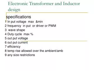
Applications of Inductor
360 likes | 689 Vues
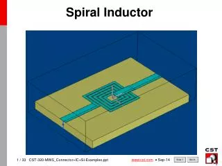
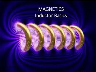
Applications of Inductor. Section 6.4. Magnetic Field Applications of Electromagnetism Transformer. Magnetic Field. Flux lines are used to represent the strength and the direction of the field. The flux lines are always drawn from the north pole to the south pole .

Applications of Inductor
E N D
Presentation Transcript
Applications of Inductor Section 6.4
Magnetic Field • Applications of Electromagnetism • Transformer
Magnetic Field • Flux lines are used to represent the strength • and the direction of the field. • The flux lines are always drawn from the north pole to the south pole.
Flux Lines of magnets Unlike Poles Attract Like Poles Repel
How materials become magnetized • Ferromagnetic Materials such as iron and nickel become magnetized when • Placed in the magnetic field of a magnet • Objects become magnetized (i.e. they become magnets themselves) under the • Influence of the permanent magnetic field and become attracted to the magnet. • When removed from the magnetic field, the objects tends to lose its magnetism. • Ferromagnetic materials have minute magnetic domains created within their • atomic structure.
Application 1: Magnetic switch When the magnet is near the switch mechanism, the switch is closed. When the magnet is moved away, the spring pulls the arm open.
Magnetic Field Note: The field is stronger closer to the conductor and becomes weaker with increasing distance from the conductor.
Right-Hand Rule Thumb: Points in the direction of current Fingers: point in the direction of the magnetic lines of force.
Application #1: Electromagnet When the coil of wire is connected to a battery, there is current. A magnetic field is established.
Solenoid • A basic solenoid consists of three parts: (Section 10-3) • 1. Coil • 2. A stationary iron core • A sliding core (plunger) is attached to the stationary core with a spring. • Applications: opening and closing valves and automobile door locks.
Magnetic fields in the core points from right to left. • Steps: • In the rest state, the plunger is extended. • The solenoid is energized by current through the coil, which sets up an • electromagnetic field that magnetizes both iron cores. • 3. The south pole of the stationary core attracts the north pole of the movable • coil causing it to slide inward, thus retracting the plunger and compressing the spring. • When the current is cut off, the magnetic fields collapse and the force of the • Compressed spring pushes the plunger back out.
Application #3 A relay is used to open or close electrical contacts.
When there is no coil current, the iron armature is held against the upper contact by the spring, thus providing continuity from terminal 1 to terminal 2. When energized with coil current, the armature is pulled down by the attractive force of the electromagnetic field and makes connection with the lower contact, providing continuity from terminal 1 to terminal 3.
Application #4Reed Relay • Reed is made of ferrous material. • When there is no coil current, the reeds are in the open position. • Where there is current, the reeds make contact because they are magnetized • and attract each other.
Current in: crowded flux lines above, resulting in downward force on the right. Current out: crowded flux lines below, resulting in upward force on the left.
Polarity of transformer B B I Bind Bind I I
Dot Convention (Section 6.4) Whenthe reference direction for a current enters the dotted terminal of a coil, the reference polarity of the voltage that it induces in the other coil is positive at its dotted terminal.
How to use Dot Convention in Circuit Analysis i2 leaves the dotted terminal. i2 leaves the dotted terminal, therefore, the induced voltage across L1 is negative. i1 enters the dotted terminal, therefore, the induced voltage across L2 is positive.