Download

1 / 12
130 likes | 361 Vues
Capacitor and Inductor Using PSpice. First Edition: 18/8/09. I1. C1. R1. Modeling Capacitor in PSpice. We have to put a big resistor (e.g. 1G) across a capacitor to provide a DC current path to ground.

E N D
Capacitor and Inductor Using PSpice First Edition: 18/8/09
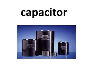
I1 C1 R1 Modeling Capacitor in PSpice • We have to put a big resistor (e.g. 1G) across a capacitor to provide a DC current path to ground. • This is because a capacitor acts as open circuit to DC (No DC path is provided by capacitor). PSpice always requires a DC path to ground for its calculation.
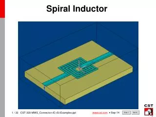
Modeling Inductor in PSpice R1 L1 V1 • We have to put a small resistor (e.g. 1u) in series with an inductor to avoid the DC current in the inductance infinitely large. • This is because an inductor acts as a short circuit to DC.
I1 C1 R1 (2ms,100) (0,0) Modeling PWL Sources (I or V) R1 V1 or L1 I1 or V1 100 I1 0 1 PWL(0,0)(2ms,100) 50 V1 1 0 PWL(0,0)(2ms,100) or 0 0s 0.5ms 1.0ms 1.5ms 2.0ms 2.5ms 3.0ms 3.5ms 4.0ms Time
To Set Analysis Request • Type of Analysis: Transient • General format: .TRAN TSTEP TSTOP <TSTART <TMAX>> Example: .TRAN 5u 5m 0 5u or.TRAN 5m 5 0 5m • TSTEP and TMAX determine the time increment. To make the thing simpler, set the same values for both TSTEP and TMAX. If the time increment is not small enough, the plot will not be smooth. • PSpice will generate data from 0 (TSTART) to 5ms (TSTOP) with the time increment of 5u (TSTEP or TMAX). So, at least 1000 data will be generated.
To Get Add Trace Expression * V(1) ic(t) Capacitor Voltage ic(t) Capacitor Current I(C1) V(1)*I(C1) vc(t)ic(t) Capacitor Power Capacitor energy S(V(1)*I(C1)) * What you will really type in the trace expression: box depends on your own netlist description.
I1 C1 R1 EXAMPLE 6-1 300 Capacitor Voltage 200 Capacitor Current 100 0 0s 0.5ms 1.0ms 1.5ms 2.0ms 2.5ms 3.0ms 3.5ms 4.0ms V(1) I(C1) Time
Capacitor voltage 8.0 V1 4.0 C1 R1 0 -4.0 -10.0 V(1) 400m Capacitor current 0 -400m 0s 0.5ms 1.0ms 1.5ms 2.0ms 2.5ms 3.0ms I(C1) Time EXAMPLE 6-2
V1 C1 R1 40 Power 0 -40 V(1) * I(C1) 40 Energy 20 0 0s 0.5s 1.0s 1.5s 2.0s 2.5s 3.0s 3.5s 4.0s 4.5s 5.0s Time S(I(C1) * V(1)) EXAMPLE 6-3
R1 L1 V1 30 0 -10 V(1) 1.0A 0A 0s 0.5ms 1.0ms 1.5ms 2.0ms 2.5ms 3.0ms 3.5ms 4.0ms Time I(L1) EXAMPLE 6-4 V(1) I(L1)
Cursor toolbar Cursor Peak Cursor Search Mark Label Using Toggle Cursor Probe toolbar Toggle Cursor 1. By clicking Toggle Cursor toolbar, we will get access to Cursor toolbar. Cursor Peak: to get the peak point on the plot. Mark label: to mark the data point on the plot. Cursor Search: to search data point on the plot. For example, by typing SFXval(3s) in Search Command box, the Probe Cursor will point at x=3s.
Using Toggle Cursor Toggle Cursor Toolbar is used to get access to data points on a plot through the Probe Cursor. We can toggle the display of the Probe cursor on and off by clicking the Toggle Cursor toolbar. 2. Also, by clicking the cursor toolbar, we will be given access to two cursors. One of the cursors is controlled by the left mouse button [A1 = (x,y)] and one is controlled by the right mouse button [A2 = (x,y)]. A small window labeled Probe Cursor gives the values at each of the cursors as well as the difference between them. We can also finely move the cursors by using left-arrow and right-arrow on the keyboard. 3. Marking a specific voltage/current level. By clicking Mark Label toolbar will label the specific point on the plot, which is pointed to by the cursor that was last moved.