PSPICE
PSPICE. Introduction. SPICE is a general-purpose circuit simulation program for nonlinear DC, nonlinear transient, and linear AC analyses.


PSPICE
E N D
Presentation Transcript
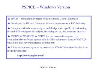
Introduction SPICE is a general-purpose circuit simulation program for nonlinear DC, nonlinear transient, and linear AC analyses. Circuits may contain resistors, capacitors, inductors, mutual inductors, independent voltage and current sources, four types of dependent sources, lossless and lossy transmission lines (two separate implementations), switches, uniform distributed RC lines, and the five most common semiconductor devices: diodes, BJTs, JFETs, MOSFETs.
Types of Analysis AC Small-Signal Analysis Transient Analysis Pole-Zero Analysis Sensitivity Analysis Noise Analysis
Circuit Description The circuit to be analyzed is described to SPICE by a set of element lines, which define the circuit topology and element values, and a set of control lines, which define the model parameters and the run controls. The first line in the input file must be the title, and the last line must be ".END" . The order of the remaining lines is arbitrary Each element in the circuit is specified by an element line that contains the element name, the circuit nodes to which the element is connected, and the values of the parameters that determine the electrical characteristics of the element. The first letter of the element name specifies the element type.
Circuit Description Title Line: The title line must be the first in the input file. Example: POWER AMPLIFIER CIRCUIT .END Line: .END The "End" line must always be the last in the input file. Comments: General Form: * <any comment> The asterisk in the first column indicates that this line is a comment line. Comment lines may be placed anywhere in the circuit description. Examples: * RF=1K Gain should be 100 * Check open-loop gain and phase margin
CIRCUIT ELEMENTS AND MODELS Resistors: General form: RX N1 N2 VALUE N1 and N2 are the two element nodes. VALUE is the resistance (in ohms) but not zero. Examples: R1 1 2 100 RC1 12 17 1K
CIRCUIT ELEMENTS AND MODELS Capacitors: General form: CX N+ N- VALUE <IC=INCOND> N+ and N- are the positive and negative element nodes, respectively. VALUE is the capacitance in Farads. The (optional) initial condition is the initial (time- zero) value of capacitor voltage (in Volts). Examples: CBYP 13 0 1UF COSC 17 23 10U IC=3V
CIRCUIT ELEMENTS AND MODELS Inductors: General form: LY N+ N- VALUE <IC=INCOND> N+ and N- are the positive and negative element nodes, respectively. VALUE is the inductance in Henry. The (optional) initial condition is the initial (time- zero) value of inductor current (in Amps) that flows from N+, through the inductor, to N-.
VOLTAGE AND CURRENT SOURCES Independent Sources: General form: VX N+ N- <<DC> DC/TRAN VALUE> <AC<ACMAG<ACPHASE>>> + <DISTOF1 <F1MAG <F1PHASE>>> <DISTOF2 <F2MAG <F2PHASE>>> IY N+ N- <<DC> DC/TRAN VALUE> <AC <ACMAG <ACPHASE>>> + <DISTOF1 <F1MAG <F1PHASE>>> <DISTOF2 <F2MAG <F2PHASE>>> N+ and N- are the positive and negative nodes, respectively. DC/TRAN is the DC and transient analysis value of the source. If the source value is zero both for DC and transient analyses, this value can be omitted.
VOLTAGE AND CURRENT SOURCES ACMAG is the AC magnitude and ACPHASE is the AC phase. The source is set to this value in the ac analysis. If ACMAG is omitted following the keyword AC, a value of unity is assumed. If ACPHASE is omitted, a value of zero is assumed. DISTOF1 and DISTOF2 are the keywords that specify that the independent source has distortion inputs at the frequencies F1 and F2 respectively. The keywords may be followed by an optional magnitude and phase. The default values of the magnitude and phase are 1.0 and 0.0 respectively. Examples: VCC 10 0 DC 6 VIN 13 2 0.001 AC 1 SIN(0 1 1MEG) ISRC 23 21 AC 0.333 45.0 SFFM(0 1 10K 5 1K)
VOLTAGE AND CURRENT SOURCES Sinusoidal: General form: SIN(VO VA FREQ TD THETA) Examples: VIN 3 0 SIN(0 1 100MEG 1NS 1E10)
TRANSISTORS AND DIODES Junction Diodes: General form: DX N+ N- MNAME <AREA> <OFF> <IC=VD> <TEMP=T> N+ and N- are the positive and negative nodes, respectively. MNAME is the model name, AREA is the area factor, and OFF indicates an (optional) starting condition on the device for DC analysis. If the area factor is omitted, a value of 1.0 is assumed. The (optional) initial condition specification using IC=VD is intended for use when a transient analysis is desired starting from other than the quiescent operating point. The (optional)TEMP value is the temperature at which this device is to operate Examples: DBRIDGE 2 10 DIODE1 DCLMP 3 7 DMOD 3.0 IC=0.2
TRANSISTORS AND DIODES Bipolar Junction Transistors (BJTs): General form: QXX NC NB NE <NS> MNAME <AREA> <OFF> <IC=VBE, VCE> <TEMP=T> NC, NB, and NE are the collector, base, and emitter nodes, respectively. NS is the (optional) substrate node. If unspecified, ground is used. MNAME is the model name, AREA is the area factor, and OFF indicates an (optional) initial condition on the device for the DC analysis. If the area factor is omitted, a value of 1.0 is assumed. The (optional) initial condition specification using IC=VBE, VCE is intended for use when a transient analysis is desired starting from other than the quiescent operating point. The (optional) TEMP value is the temperature at which this device is to operate Examples: Q23 10 24 13 QMOD IC=0.6, 5.0 Q50A 11 26 4 20 MOD1
TRANSISTORS AND DIODES Junction Field-Effect Transistors (JFETs): General form: JX ND NG NS MNAME <AREA> <OFF> <IC=VDS, VGS> <TEMP=T> Examples: J1 7 2 3 JM1 OFF
ANALYSES .AC: Small-Signal AC Analysis: General form: .AC DEC ND FSTART FSTOP .AC OCT NO FSTART FSTOP .AC LIN NP FSTART FSTOP DEC stands for decade variation, and ND is the number of points per decade. OCT stands for octave variation, and NO is the number of points per octave. LIN stands for linear variation, and NP is the number of points. FSTART is the starting frequency, and FSTOP is the final frequency. If this line is included in the input file, SPICE performs an AC analysis of the circuit over the specified frequency range. Note that in order for this analysis to be meaningful, at least one independent source must have been specified with an ac value. Examples: .AC DEC 10 1 10K .AC DEC 10 1K 100MEG .AC LIN 100 1 100HZ
ANALYSES .DC: DC Transfer Function: General form: .DC SRCNAM VSTART VSTOP VINCR [SRC2 START2 STOP2 INCR2] The DC line defines the DC transfer curve source and sweep limits. SRCNAM is the name of an independent voltage or current source. VSTART, VSTOP, and VINCR are the starting, final, and incrementing values respectively. Examples: .DC VIN 0.25 5.0 0.25 .DC VDS 0 10 .5 VGS 0 5 1 .DC VCE 0 10 .25 IB 0 10U 1U The first example causes the value of the voltage source VIN to be swept from 0.25 Volts to 5.0 Volts in increments of 0.25 Volts. A second source (SRC2) may optionally be specified with associated sweep parameters. In this case, the first source is swept over its range for each value of the second source. This option can be useful for obtaining semiconductor device output characteristics.
ANALYSES .TRAN: Transient Analysis: General form: .TRAN TSTEP TSTOP <TSTART <TMAX>> TSTEP is the suggested computing increment. TSTOP is the final time, and TSTART is the initial time. If TSTART is omitted, it is assumed to be zero. The transient analysis always begins at time zero. In the interval <zero, TSTART>, the circuit is analyzed (to reach a steady state), but no outputs are stored. In the interval <TSTART, TSTOP>, the circuit is analyzed and outputs are stored. TMAX is the maximum step-size that SPICE uses; for default, the program chooses either TSTEP or (TSTOP-TSTART)/50.0, whichever is smaller. TMAX is useful when one wishes to guarantee a computing interval which is smaller than the printer increment, TSTEP. Examples: .TRAN 1NS 100NS .TRAN 1NS 1000NS 500NS .TRAN 10NS 1US
ANALYSES .PROBE (Probe): The .PROBE command writes the results from DC, AC, and transient analyses to a data file used by Probe. General form: .PROBE[/CSDF][output variable]* Examples: .PROBE .PROBE V(3) V(2,3) V(R1) I(VIN) I(R2) IB(Q13) VBE(Q13) .PROBE/CSDF The first example (with no output variables) writes all the node voltages and all the device currents to the data file. The list of device currents written is the same as the device currents allowed as output variables. The second example writes only those output variables specified to the data file, to restrict the size of the data file. The third example creates a data file in a text format using the Common Simulation Data File(CSDF) format, not a binary format. This format is used for transfers between different computer families. CSDF files are larger than regular text files.
WORKING WITH PSPICE • To launch PSpice: Start All programs OrCAD 16.0 PSpice • Go to File New Text File • Write the spice netlist in the Text file and save the file with extension “.cir” • Instead of above two steps, we can write the Net list in a notepad and save it with extension “.cir” and open that file from File Open filename.cir
CREATING SPICE NETLIST • To create a spice netlist first identify the nodes in the circuit diagram as shown below and write the netlist based on the nodes assigned to circuit diagram
EXAMPLES: • Voltage Divider: netlist: Voltage Divider Circuit Vin 1 0 3V R1 1 2 1k R2 2 0 2k .dc Vin 0 10 .1 .probe V(2)
Low-pass filter: netlist: Low-Pass Filter Vin 1 0 AC 1V pulse(0 1 0 1m 1m 10m 20m) R1 1 2 1k C1 2 0 1uF *.ac dec 10 1 1G .tran .1m 100m .probe