PSpice Tutorial
PSpice Tutorial. October 13, 2004. Franklin Chiang. Orcad Programs. PSpice Use “netlists” to code up circuits. Text based. Start programs Orcad Family Release 9.2 Orcad PSpice Capture Use diagrams to draw up circuits and simulate. Graphics based.

PSpice Tutorial
E N D
Presentation Transcript
PSpice Tutorial October 13, 2004 Franklin Chiang
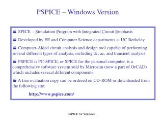
Orcad Programs • PSpice • Use “netlists” to code up circuits. Text based. • Start programs Orcad Family Release 9.2 Orcad PSpice • Capture • Use diagrams to draw up circuits and simulate. Graphics based. • Start programs Orcad Family Release 9.2 Lite Capture Lite
Startup and Basic Syntax • Start Programs Orcad Release 9.2 PSpice • File New Text file • 5 different “commands” you can use • Title: first line of code (always) • .END: last line of code (always) • Comment: line denoted by * • Element: Resistor, capacitor, etc. • Control: analysis
Passive Component Description • Resistor • R<name> <node1> <node2> <value> • Ex. R1 1 2 100 • Names should not contain comma, space, or =, or parenthesis • Capacitor • C<name> <node1> <node2> <value> • Ex CBYP 13 0 1uF • Inductor • L<name> <node1> <node2> <value>
Units in PSpice • T = tera = 1012 • G = giga = 109 • Meg = mega = 106 • k = kilo 103 • m = milli = 10-3 • u = micro = 10-6 • n = nano = 10-9 • p = pico = 10-12 • f = femto = 10-15
Source design • Independent Voltage Source • V<name> <+node> <-node> <dc/ac> <value> • VCC 10 0 DC 6 • Independent Current Source • I<name> <+node> <-node> <dc/ac> <value> • I_in 10 0 AC 3m
Voltage Sources • DC: Vname n+ n- DC <value> • AC: Vname n+ n- AC <magnitude> <phase> • Transient: • Vname n+ n- sin(Vo Va freq td damp) • Vname n+ n- pulse(V1 V2 td tr tf PW T) • Vname n+ n- PWL(t1, v1, t2, v2, …, tn, vn)
Active Devices (transistors!) • Usually given a model file as text file • Include it into pspice using: • .lib <name of file> • ex: .lib 115cmodel.txt • Make sure text file is in same directory
Including your own model files • .model <name> <type> <parameters….> • .model QPNP PNP(Is=650.6E-18 Xti=3 Eg=1.11 Vaf=100 Bf=150 Ne=1.829 + Ise=54.81f Ikf=1.079 Xtb=1.5 Br=3.563 Nc=2 Isc=0 Ikr=0 Rc=.715 + Cjc=14.76p Mjc=.5383 Vjc=.75 Fc=.5 Cje=19.82p Mje=.3357 Vje=.75 + Tr=111.3n Tf=603.7p Itf=.65 Vtf=5 Xtf=1.7 Rb=10) • .model QNPN NPN(Is=14.34f Xti=3 Eg=1.11 Vaf=100 Bf=150 Ne=1.307 + Ise=14.34f Ikf=.2847 Xtb=1.5 Br=6.092 Nc=2 Isc=0 Ikr=0 Rc=1 + Cjc=7.306p Mjc=.3416 Vjc=.75 Fc=.5 Cje=22.01p Mje=.377 Vje=.75 + Tr=46.91n Tf=411.1p Itf=.6 Vtf=1.7 Xtf=3 Rb=10) • Copy, paste.
Declaring transistors • BJT: • Q<name> <NC> <NB> <NE> <model> • Ex. Q23 10 24 13 npn • MOSFET: • M<name> <ND> <NG> <NS> <NB> <model> <various parameters> • M1 24 2 0 20 nmos • M2 2 9 3 0 pmos L=10u W=5u AD=100p AS=100p PD=40u PS=40u
Building a circuit 1 2 • First, draw the diagram • Label nodes • Code in Pspice 3 3 4 0
Analysis Types • DC Analysis • DC transfer curve source and sweep • .dc <source> <vstart> <vstop> <vincr> [src2 start2 stop2 incr2] • .DC VIN 0.25 5.0 0.25 • .DC VDS 0 10 .5 VGS 0 5 1 • “nested sweep”: for each VDS, sweep VGS from 0 to 5 incrementing by 1 each time. So total number of operations would be 20 * 5 = 100
Analysis Types • Operating Point • .op • Calculates dc operating point of circuit with inductors shorted and capacitors open. • Useful in checking your work. • Results put in .txt file
Analysis types • AC small signal • computes the ac output variables as a function of frequency • first computes the dc operating point of the circuit and determines linearized, small-signal models for all of the nonlinear devices in the • resultant linear circuit is then analyzed over a user-specified range of frequencies • Can be used to compute noise!
Analysis Types • AC Analysis (cont) • .AC DEC ND FSTART FSTOP • Dec = decade variation, ND = pts. / decade • .AC LIN NP FSTART FSTOP • Lin = linear variation, NP = # pts • .NOISE OUTV INSRC NUMS • OUTV = output voltage which defines summing point • INSRC = name of independent source which is the noise input reference • NUMS = summary interval
Analysis Types • Transient (.tran <step> <stop> <start>) • The transient analysis portion of SPICE computes the transient output variables as a function of time over a user specified time interval • The initial conditions are automatically determined by a dc analysis • Useful for 115C • .tran 1ns 1000ns 500ns
Back to Resistor Bridge • Ex. Find voltage across R3 when Vin = 10V
Transistor examples: IV curve • Plot I-V characteristic of NMOS with: • W = 1.2um • L = 0.25 um • Set Vdd = Vg = 2.5V, Vs = 0V D G ID S
Solution: 3 • 1) Draw circuit with sources • 2) Label nodes! • 3) Code in spice 2 0