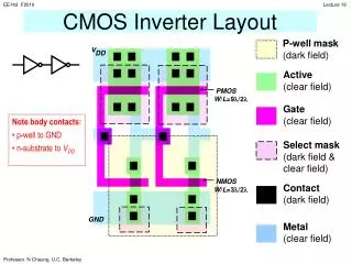
CMOS Inverter Using PSpice
CMOS Inverter Using PSpice. Which doesn’t look like the I-V curve of a typical CMOS inverter. MOSFET Models: Threshold Voltage. IRF150 Vto = 2.831 IRF9140 Vto = - 3.67 They overlap when Vin is limited to 0-5V.

CMOS Inverter Using PSpice
E N D
Presentation Transcript
Which doesn’t look like the I-V curve of a typical CMOS inverter.
MOSFET Models: Threshold Voltage • IRF150 • Vto = 2.831 • IRF9140 • Vto = -3.67 • They overlap when Vin is limited to 0-5V. • There is never a value of input voltage where both transistors are in pinch-off/saturation or triode/nonsaturation.
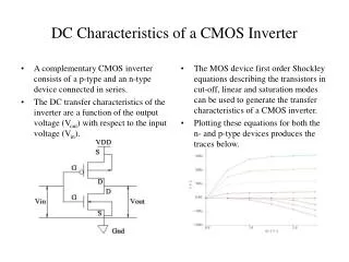
What to do? • To get a more common voltage transfer characteristic for a CMOS inverter: • you need to use a higher voltage range for Vin and VDD • Older CMOS used 7.5,12,15V, and even +/- 15V. • or • you change Vto in the device model when Vin is between 0-5V and VDD= 5V.
IRF150 Kp=20.53u W=.3 L=2u IRF9140 Kp=10.15u W=1.9 L=2u IRF150 Kn = 5.05mA/V2 IRF 9140 Kp = 9.64mA/V2 Why is the peak current not a VDD/2?
Closer to Ideal • Still have differences between • the NMOS and PMOS PSpice models • and • differences between the two PSpice models and our piecewise models