Download
1 / 48
490 likes | 639 Vues
EN. Reorganization of East Area Beam Lines Status Report at ATOP meeting . L.Gatignon, 06/03/2009. OUTLINE:. Motivation Guiding principles and strategy Constraints from physics programme Contain radiation Magnets available

E N D
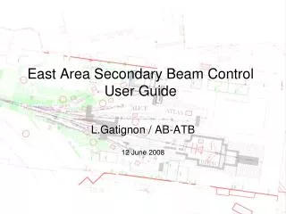
EN Reorganization of East Area Beam LinesStatus Report at ATOP meeting L.Gatignon, 06/03/2009
OUTLINE: • Motivation • Guiding principles and strategyConstraints from physics programmeContain radiation Magnetsavailable • Primary beamsOptimize choice of magnets DIRAC, Irradiation facilities • Test beamsOptics, layout Performance • Practical implementationMagnets Shielding • Time line • Conclusions Reorganisation of East Area Beam Lines
WHY A NEW LAYOUT FOR THE EAST AREA Triggeredby ABOC/ATC days in 2007 • Splitters lead to high beam losses in critical regions- high radiation levels - no beam loss monitors! • Catastrophic situation of magnets- 63 magnets of 22 different types, many critically weak and/or no spares - need 2 weeks to open & close concrete roof shield + cooldown + repair - space very tight, access extremely difficult - high radiation levels - EA has only 8% of #magnets in NA, but needs same #FTE to maintain • No remote control for most systems (motors in particular)No high level control system, no beam files Grossly insufficient beam instrumentation– somewhat improved since then Recommendation: global review of East Area Note: Operational difficulties with F61N.BVT01 in 2008, T10 only 6 GeV due to two Q800 (smoke traces!), three Q120’s being replaced now… Reorganisation of East Area Beam Lines
To liberate PS cycles for DIRAC and still requests being added, due to pressure on beam time! = Tests = CLOUD THE EAST AREA CONTINUES TO BE POPULAR: Reorganisation of East Area Beam Lines
BASIC PRINCIPLES FOR NEW EAST AREA • Use fewer types of reliable magnets with spares • Reduce roof shielded areas and ease access to equipment • Keep radiation restricted to upstream areas as much as possible • Keep T8 beam and DIRAC installed as it is until the end of DIRAC,or for IRRAD in case they take over the DIRAC location • Replace SMH1 and F61S.BHZ1 by two MCB magnets in PPM mode,i.e. no more splitter (F61S.BHZ01 replacement already done). • Could also serve IRRAD as now, through air, however not from ZT7.BHZ01but from F61S.BHZ02 • Design new beam(s) to 1 (or 2) “North target” marguerite(s)- two decoupled beams, but at the cost of cycle efficiency - two beams coupled by “wobbling station”, coupled but higher cycle efficiency • Test beams can provide pure hadron and muon secondary beams up to 15 GeV/cand pure (> 95%) electron beams from g conversion (up to about 10 GeV/c) Inspired by and similar in spirit to West Area rebuild in the end of the 1990’s! Reorganisation of East Area Beam Lines
at maximum strength compatible with PPM MCB MCB “Poor man’s wobble” ? Keep test beam dumpavailable as before, put now also PPM Reorganisation of East Area Beam Lines
End of primary beam: 1. Switch Loss of cycle efficiency, but two performing, decoupled test beams or 2. Wobbling2x better cycle efficiency but some coupling. Can run as in the past (i.e. on fixed axis), but with same restrictions as in the past Concentrate on this option for the moment Reorganisation of East Area Beam Lines
Suppress T11 Dismount T7 beam and deflect towards IRRAD with F61S.BHZ02 Suppress T7 Reorganisation of East Area Beam Lines
Uses “dummy magnets” ~5x better transmission than present lines! m± pure h± e± Reorganisation of East Area Beam Lines
MAGNETS List of magnets available for the new area (only the green ones). Also documentation! Could eventually be complemented with magnets from NA stock (?) Received on 30/09/2008 Reorganisation of East Area Beam Lines
Please note that this list is based on huge efforts (over about one year!) by the TE/MCS team (D.Bodart, D.Tommasini et al), including a test campaign of 100 spare magnets in T7 zone Reorganisation of East Area Beam Lines
Start with the primary beams • As short as possible • Compatibility as much as possible with DIRAC • Respect list of magnets wherever possiblei.e. no MNP23, few M105,few narrow magnets! • Maximize lateral separation between beam lines • Try to have primary target(s) in isolated zone (RP-wise) Make coherent ‘Beatch’ files from extraction to targets (Dirac, North)and consistent optics files, describing correctly phase space from extraction: dirac2011, north2011old files: dirac2008, north2008t9y2011, t10y2011 Reorganisation of East Area Beam Lines
Not significantly different from 2008 Different central trajectory + changes of magnet types Reorganisation of East Area Beam Lines
SECONDARY BEAM OPTICS FOR “T9++ BEAM” – UP TO 15 GeV/c Reorganisation of East Area Beam Lines Even better transmission than generic optics!
SECONDARY BEAM OPTICS FOR “T10++ BEAM” – UP TO 12 GeV/c Reorganisation of East Area Beam Lines
TURTLE SIMULATION (for C1ACCV=C2ACCH = ±40 mm, C3DP = ±1 mm) Y in mm X in mm Reorganisation of East Area Beam Lines
Dp/p in % Reorganisation of East Area Beam Lines
SCHEMATIC LAYOUT OF THE TWO SECONDARY BEAMS (inspired by “West Area 2000” approach) Reorganisation of East Area Beam Lines
30 mrad prod. angle (vertical) PROTONS DUMPED Reorganisation of East Area Beam Lines
Preliminary POWER SUPPLY REQUIREMENTS PRIMARY BEAMS *) Same limit as before green = as before red = swapped with other elements Reorganisation of East Area Beam Lines
Preliminary POWER SUPPLY REQUIREMENTS SECONDARY BEAMS All existing in present T9, T10, T11. Spectrometers (existing!) to be added Detailed attribution remains to be optimised! *) Could be connected in series Reorganisation of East Area Beam Lines
SPECIAL BEAM OPTICS FOR CLOUD (Beam spot ~2x2 m!!!) Reorganisation of East Area Beam Lines
Beam Profile at CLOUD X [mm] Flux [arbitrary units] Y [mm] X [mm] Y [mm] Reorganisation of East Area Beam Lines
And this is how it looks ‘on the floor’: Reorganisation of East Area Beam Lines
The shapes are made as overlays on the old, respectively new layout drawing, on the same scales Primary zone Open PS zone DIRAC PS zone Primary zone Open Sec. zone DIRAC Old layout: New layout: Reorganisation of East Area Beam Lines
“T10” MCB to switch from“T9” to “T10” in PPM mode (55 mrad) 55 mr 40 mr 2x2 MDX to sweep “T9” M200 40 mrad Bend to separate North branches from DIRAC How to run two test beams simultaneously So far: Layout for switch, i.e. run two test beams on different cycles 8.94 m 4.54 m Reorganisation of East Area Beam Lines
Alternative solution: qprod = 30 mradH 35 mradV 46 mrad MDV1 “T10” MCB 55 mr M100 M100 sweeper for both 30 mr 12.5 mr 30 mr “T9” ~5.54 m qprod = 30 mradH 30 mradV 42 mrad Advantage: operate both beams on the same cycle Disadvantages: Larger production angles (degrade with q2 !) Electron sweeping on/off for both beams Shorten T9,T10 front-ends by 1 m, hence 5.5 cm closer together Reorganisation of East Area Beam Lines
M200 MDV1 “T10” MCB e.g. 55 mr M200 30 mr 12.5 mr 30 mr or “T9” At least 4 m longer Or a complete “Wobbling” as in North Area Advantage: Get simultaneous operation with larger decoupling (as in North Area T2) But have to move T9 and T10 beams downstream by at least 4 metres, i.e. into transit areas Reorganisation of East Area Beam Lines
What does this mean? • Compatibility with requirements from DIRAC/IRRAD and CLOUD • More flexible and better test beams, but (effectively <) 1 lessHigher top momenta, small production angles, choice of particle type • Only use agreed ‘healthy’ magnets with sufficient sparesAll magnets and rectifiers exist – reduced cost • Primary beam is dumped almost immediately after targetHigh (also induced) radiation levels restricted to minimal areas • Very restricted number of magnets is under heavy roof shieldingThe ones in a limited zone following the primary area have only a thin roof shield. Many have no roof shielding.RP simulations are required to see whether the latter shield can be avoided • Restricted material cost but lots of reshuffling of lines and shielding Reorganisation of East Area Beam Lines
Side remark: In 2005 a proposal was made to upgrade the controls of the East Area. For the moment in the East Area there is: • no remote control / readout of collimators • control of magnet currents only by working sets and knobs • no easy and convenient beam files • no remote reading of access system and vacuum state • no user applications for reading of beam instrumentationHowever, one delay wire chamber + a scintillator were added per beam since then It seems that this could be an occasion to migrate the East Area controls to Cesar(i.e. the recently upgraded North Area controls). At the time the resource estimate (excluding DWC + scints) were about 80 kCHFfor VME crates + Cerenkov upgrades plus a number of man months on the software side. Now part of this upgrade has been done already (timing, VME). Reorganisation of East Area Beam Lines
Rebuild of parts inside PS and of primary zone in shutdown 2010/11,provided CLOUD has completed its Mk2 program Continue construction of test beams during the 2011 runCould probably continue operation of DIRAC during 2011 withsome additional local shielding at exit of the primary zone Total duration of project: first estimates 8-12 months Proposed time line • CLOUD changes from Mk2 to Mk3 module in 2011 (tbc)This requires a larger beam and a larger zone (T11 → T9B zone)It seems reasonable to synchronize the EA modifications with this change • DIRAC / IRRAD future not well understood at this momentbut new design is essentially decoupled from this question Reorganisation of East Area Beam Lines
SUMMARY • A conceptual design has been presented for a new East AreaCompatible with approved experiments Better, more flexible test beams. Users would benefit! • Uses reliable hardware with spares • Restrict radiation hot spots to restricted regions • Easier access to most of equipment in case of failure • Modest material cost, but work to reshuffle lines and shielding • Could start in shutdown 2010/2011 if funding available • Engineering studies needed to finalize RP aspects and resource estimates Reorganisation of East Area Beam Lines
Thanks for your attention Thanks also for very valuable input and help from many people. In particular I want to mention: F.Bordry, J.Lettry, W.Kalbreier, D.Tommasini, D.Bodart, C.Rembser, E.Perez, H.Breuker, R.Steerenberg, J-L.Blanc, Th.Otto, M.Widorski, M.Lazzaroni, Y.Bonnet, … Reorganisation of East Area Beam Lines
Spare Slides Reorganisation of East Area Beam Lines
VERY PRELIMINARY ESTIMATES (tbc by engineering studies) green: can be donemostly in the shadow of other activities Total duration could be 7-8 months (?). Primary + PS zone work in 4 months? Reorganisation of East Area Beam Lines
Remember: West Area rebuild in late 1990’s Compare to East Area The proposed East Area reorganization seems of a similar scale as the rebuild of X5 and X7 (i.e. excluding the H3 part), which took at the time a total of 7 months and 500 kCHF Reorganisation of East Area Beam Lines
X5&X7 beams after upgrade in late 1990’ s: Reorganisation of East Area Beam Lines
T1+H3 modification: Reorganisation of East Area Beam Lines
Nominal Currents Reorganisation of East Area Beam Lines