Download
1 / 157
1.67k likes | 2.29k Vues
Place for logos of authors’ institutions. Optical Access and Metro Networks Module 6 (temp). Passive optical networks. Fabio Neri Jorge M. Finochietto Politecnico di Torino. Contents. Introduction Motivation Optical Access Networks Passive Optical Networks (PON) TDM-PON

E N D
Place for logos of authors’ institutions Optical Access and Metro NetworksModule 6 (temp). Passive optical networks Fabio NeriJorge M. Finochietto Politecnico di Torino
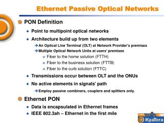
Contents • Introduction • Motivation • Optical Access Networks • Passive Optical Networks (PON) • TDM-PON • Physical Layer and Devices • Traffic Distribution/Scheduling • Power Budget • Standards • APON/BPON • EPON • GPON • WDM-PONs • Proposed solutions
The Broadband Connected Household Interactive Gaming Ethernet 10-50 Mb/s Video- Conference Set Top Box Computers 2x5 Mb/s O/E IP TV-channels +VoD services 100 Mb/s Telephone 2x20 Mb/s TriplePlay TV Real Estate services Lock Alarm Laundrybooking Energy monitoring DVR Home station HDTV
Access Network Technologies for access network: • Plain Old Telephone Service (POTS) • Asymmetric Digital Subscriber Loop (ADSL) • Cable-modems using Cable-TV (CATV) infrastructures • Power Line Communication – PLC • Wireless access technologies • Local Multipoint Distribution Service (LMDS) • WiFi/WiMax • Cellular networks • Optical access networks
xDSL Solutions Data Rate, Mbps 52 VDSL Shannon’s information theorem… (S/N-limited, here: crosstalk) 24 ADSL2+ 12 8 ADSL2 ADSL 6 Km 1 Km 2 Km 3 Km 4 Km 5 Km Length, Km Source: Ericsson • Largely deployed nowadays • Use of existing copper lines • Smooth migration/upgrade of current network • Bandwidth and reach are limited!
ADSL: User Devices • Splitter • separates data from voice signals • Modem • (de)modudulates signals at proper frequencies (e.g., in ADSL, from 25 KHz in upstream, and from 240 KHz in downstream) Voice Data
HFC Access Network tap Headend Remote node amplifiers fiber coax • CATV infrastructures are also called Hybrid Fiber Coax (HFC) • They offer a unidirectional high speed downstream channel
Fiber To The X (FTTx) $$$ $ $$ $-$$ FTTH :Fiber To The Home FTTC:Fiber To The Curb FTTB :Fiber To The Building FTTCab :Fiber To The Cabinet Service Node “Later” Internet FTTH ONT Optical Fiber Leased Line “Soon” ONT FTTB Frame/Cell OLT Relay “Later” ONU NT FTTC Telephone Twisted Pair “Soon” ONU Interactive FTTCab NT Video PON xDSL
Low Attenuation, large distances Low power consumption Large Bandwidth, many broadband users Requires new fiber installation Outside plant costs are important!! Optical Access Networks
Optical Access Networks • Point-to-Point links • Simple, standardized and mature technology • N fibers lines • 2N transcievers
Optical Access Networks • Active Optical Network • Simple, standardized and mature technology • 1 fiber line • Curb Switch power in the field • 2N+2 transcievers
Optical Access Networks • Passive Optical Network (PON) • Simple, under standardization technology • 1 fiber line • N+1 transcievers • passive devices (splitters)
PON Overview Downstream Traffic Upstream Traffic Passive Devices ODN OLT: Optical Line Terminator ONU: Optical Network Unit ODN: Optical Distribution Network
Time vs. Spectrum Sharing • Downstream point-to-multipoint network • The OLT manages the whole bandwidth • Upstream multipoint-to-point network • ONUs transmit only towards the OLT • ONUs cannot detect other ONUs transmissions • Data transmitted by ONUs may collide Need of a channel separation mechanism to fairly share bandwidth resources TDMATime Division Multiple Access WDMAWavelength Division Multiple Access
PON Evolution • TDM-PONs • Standarized • Use few wavelengths (typically 2 or 3) • Low cost and mature devices (splitters, lasers, etc.) • Limited power budget • Maximum distances 20km, Split ratios 64 • Traffic distribution • Broadcast scheme in downstream • TDMA techniques in upstream • Examples: APON/BPON, EPON & GPON • WDM-PONs • Proposed in literature and/or demonstrated • Introduce WDM techniques and devices (AWG) • Long-reach and bandwidth • Examples: CPON, LARNET, RITENET, Success-DWA…
Contents • Introduction • Motivation • Optical Access Networks • Passive Optical Networks (PON) • TDM-PON • Physical Layer and Devices • Traffic Distribution/Scheduling • Power Budget • Standards • APON/BPON • EPON • GPON • WDM-PONs • Proposed solutions
PON Physical Layer ONU ONU ONU OLT • Passive splitter/combiner(s) • Two separated channels • Downstream (OLT ONUs) • Upstream (ONUs OLT) • A 3rd channel can be used for broadcasting video ODN Passive Splitter
Optical Fiber: Attenuation 3.0 2.5 2.0 1.5 1.0 0.5 800 900 1000 1100 1200 1300 1400 1500 1600 1700 • Single Mode Fiber (SMF) to achieve large distances • ITU G.652 SMF (STD) • “water peak”attenuation renders the 1360nm–1480nm spectrum unusable for data transmission • ITU G652c/d SMF(ZWP) • “zero-water peak” First Window STD SMF Second Window ZWP SMF Third Window ATTENUATION (dB/km) 1310nm 850nm 1550nm WAVELENGTH (nm)
Optical Fiber: Chromatic Dispersion • Causes signal pulse broadening
Lasers Diodes (LD) DFB Simple FP + + gain gain l mirror cleave l mirror AR coating - - • Fabry-Perot (FP) • Cheap • Noisy • Sensitive to chromatic dispersion • Used on 1310 nm • Distributed Feedback (DFB) • More expensive • Narrow spectral width • Less sensitive to chromatic dispersion • Used on 1550 nm (or 1310 nm)
Photodiodes (PD) • PIN Photodiodes • Good optical sensitivity (-22 dBm) • Silicon for shorter ’s (eg 850nm) • InGaAs for longer ’s (eg 1310/1550nm) • Avalanche Photodiodes (APDs) • Higher sensitivity (-30 dBm) • Primarily for extended distances in Gb/s rates • Much higher cost than PIN diodes
Typical PON Configuration • Wavelengths • Transceivers
Downstream Traffic ONU ONU ONU OLT Passive Splitter • Downstream traffic is broadcasted to all ONUs • Weak security • ONUs filter data (frames) by destintation address
Downstream Traffic Scheduling A C B A A A A B B B B C C C C B B B B OLT Passive Splitter • OLT schedules traffic inside timeslots • Time Division Multiplexing (TDM) scheme • Time slots can vary from s to ms
Downstream Frame Reception C B A 7 km OLT 3 km 1 km • Each ONU receives all the frames with the same constant power • Simple receiver (low-cost) @ ONUs • Frames have preambles/markers
Upstream Traffic ONU ONU ONU OLT Passive Splitter • All ONUs share the same upstream channel • ONUs cannot exchange data directly • Collisions may occur at the splitter/combiner
Upstream Traffic Scheduling 1/4 Collision!! A C B A B B A C B B OLT Passive C Splitter • Media access mechanisms • Contention-based (similar to CSMA/CD) • ONUs cannot detect collisions due to directional properties of optical splitter/combiner • Guaranteed (TDMA, OCDMA, etc.)
Upstream Traffic Scheduling 2/4 A C B A A B C B B B OLT Passive Splitter C • In general, PON standards propose Time Division Multiplexing Access (TDMA) schemes • Upstream time slicing and assignment
Upstream Traffic Scheduling 3/4 A B C 2 1 2 1 2 2 1 1 A A A A B B B B C C C C B B B B OLT Passive Splitter • Typically, downstream traffic carries grants that schedule upstream traffic • Grant distribution must take into account the different propagation times to reach each ONU 10 km 2 km
Upstream Traffic Scheduling 4/4 A A C B 1 2 C A OLT Passive Splitter C C • PON standards define ranging mechanisms • the method of measuring the logical distance between each ONU and the OLT and determining the transmission timing such that upstream cells sent from different ONUs do not collide 10 km 2 km
Upstream Frame Reception C B A 7 km OLT 3 km Passive Splitter 1 km • The OLT receives frames with different powers • Much difficult to recover synchronism • Burst Mode Receiver (complex) @ OLT • Sets 0-1 threshold on a burst basis A B A B
Power Budget • Maximum optical power loss in the ODN • Difference between the TX power and the sensitivity of the RX • Considers attenuation of fiber, connectors, splices, splitters, etc.
1x2 Splitter 1xN Splitter Passive Splitters • Every time the signal is split two ways, the signal is reduced by 10log(0.5)=3dB • Loss 3dB log2(#ONUs)
Splitter/Couplers Configurations 4-stage 8x8 3-stage 8x8
Transceiver Assumptions • Upstream (@1310nm)Power Budget = 30 dB • Downstream (@1490nm)Power Budget = 22 dB
Video Distribution over PONs • Video can be distributed in several ways • RF video signal (overlay video) • Uses the same technology employed in cable TV networks • Requires a dedicated wavelength and high-power • Supports both analog and digital channels • IP video signal (integrated video) • Uses IP protocol to delivery video services • Can use the same wavelength as data and voice • Video head end can be shared among many networks/platforms
RF Video Signal ONU ONU ONU OLT • A 3rd channel (1550nm) can be used for video • A high-power signal is required for video • The video signal is amplified by an EDFA at the OLT video EDFA video Passive video Splitter video
RF Video Issue: Brillouin Scattering • All optical fibers have a physical limitation known as stimulated Brillouin scattering (SBS) • SBS occurs when a high power optical signal over relatively long length (>8km) fiber generates variations in the fiber’s optical properties and scatters optical signals in the reverse direction. • As power levels increase, so does the effect, resulting in transmitter signal loss and noticeable video signal degradation on a subscriber’s TV • In general, this results in a power budget of 21 dB(@1310nm)
Upstream Analysis (Conventional ODN) • Considers only fiber and splitter attenuation Each split costs 7.4 km (12.3%)
Downstream Analysis (Conv. ODN) • Considers only fiber and splitter attenuation Each split costs 12.3 km (14.7%)
RF Video Analysis (Conventional ODN) • Considers only fiber and splitter attenuation Each split costs 12.3 km (16.1%)
Upstream Analysis (Low loss ODN) • Considers only fiber and splitter attenuation Each split costs 8.5 km (11.3%)
Downstream Analysis (Low loss ODN) • Considers only fiber and splitter attenuation Each split costs 17 km (14.8%)
RF Video Analysis (Low loss ODN) • Considers only fiber and splitter attenuation Each split costs 17 km (16.2%)
Reach/Split Ratio Improvement • Use of Forward Error Correction (FEC) techniques • ITU-T G.795 • Red Salomon Code • Low frame processing delay (12s) • 6% overhead • Upto 5.5dB gain • APD electrical gain (limited by shot noise) • PIN ½ electrical gain (limited by thermal noise) • Improvements • Increase 1:32 splits @ 10km • Allow 1:16 km @ 20km
Which one is a better design? Fiber: 0.3dB/kmSplitter: 3dB/split 1 km 10 km x32 10 km x32 1 km a) b)