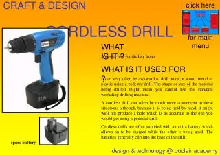
Cordless Electric Nailer
Designing a portable, battery-powered nailer with an efficient DC motor controller. Objectives, system outline, testing, and challenges.

Cordless Electric Nailer
E N D
Presentation Transcript
Cordless Electric Nailer Team 27: Nithin Reddy and Mohammad FarooqShaik Ece 445 Senior Design Project Team 27
Introduction A battery powered nailer will provide the user with a sense of portability that current models do not. Our goal is to develop an efficient DC motor controller for the mechanical component of the nailer.
Objectives • Design a low powered DC motor Controller. • Inexpensive. • Develop enough energy to drive a nail. • Create a battery monitoring system.
System Specifications • Input: • 10-18 Vdc • Output: • 15 Vdc±2% • Power Ratings: • 250W Continuous • 500W Peak for 1 minute
System Outline PowerSupply BatteryChargeDisplay PWM UC 3825 Buck Converter Mechanical Component DC Motor H-Bridge Driver LS 7260 H-Bridge Control Module Voltage Regulator Module
Battery Charge Display • Consists of 3 LEDs • Green – Battery is full. • Yellow – Battery is 60-70% full. • Red – Battery is getting low • Variable resistors can adjust the thresholds of the 3 LEDs
Battery Charge Display Testing • Circuit was tested by applying a variety of voltages. • The respective LED lights up for the voltage applied. • If the LED did not light up, it was tested to see if the LED was faulty.
Battery Charge Display Vo >14.5 volts 14.5 V> Vo > 12.5 V 12.5 V> Vo Vo = Battery voltage
Control Module • Pulse Width Modulation (UC3825) • Compares the output voltage from the voltage divider circuit to the internal reference and adjusts the duty cycle accordingly. • H bridge driver (LS7260) • Direct drive control of MOSFETs. • Controls direction of DC motor. • Ability to stop the motor at any instant.
Buck Converter Simulated Boost Converter Output • Step down DC-DC converter. • Maintains constant output of 15 volts.
Buck Converter Testing • Tested the buck converter circuit with varying voltages. • Ensured that the output voltage was 15 volts regardless.
H Bridge • 4 MOSFETS( 2 P type and 2 N type). • 2 MOSFETS are on at one time. • Controls the direction of the motor.
H Bridge • When S1 and S4 are on, the motor moves in an anticlockwise direction • When S2 and S3 are on, the motor moves in a clockwise direction
Mechanical Component • Currently being created by mechanical engineering senior design team • Motor will rotate and will cause spring to compress and expand. Expanded Spring Collapsed Spring
Successes • Battery powered. • Low Power Requirement. • Inexpensive. • Ability to control motor direction.
Difficulties • Speed control of the DC motor with the PWM chip. • Winding of the Inductor. • Searching for high current resistant MOSFETS. • Understanding Chip Functionality.
Recommendations • Finalize circuit design before submitting a PCB request. • Obtain compatible high power motors to test at desired power levels. • Use Power Lab: Less crowded, Familiar Equipment and access to motors. • PCB layout to improve efficiency and avoid parasitics (stray capacitance and inductance).