Elevator Controller System Interface Design
160 likes | 257 Vues
A detailed system interface design for elevator controllers, including Request Resolver and Unit Control functions. Describes FSM model and Sequential program.

Elevator Controller System Interface Design
E N D
Presentation Transcript
2-Hardware Design of Embedded Processors (cont.) Advanced Approaches
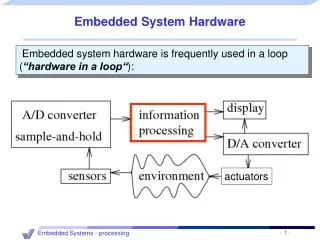
Partial English description System interface “Move the elevator either up or down to reach the requested floor. Once at the requested floor, open the door for at least 10 seconds, and keep it open until the requested floor changes. Ensure the door is never open while moving. Don’t change directions unless there are no higher requests when moving up or no lower requests when moving down…” up Unit Control down open floor req Request Resolver buttons inside elevator b1 b2 ... bN up1 up/down buttons on each floor up2 dn2 up3 dn3 ... dnN Example: An elevator controller • Simple elevator controller • Request Resolver resolves various floor requests into single requested floor • Unit Control moves elevator to this requested floor • Try capturing in C...
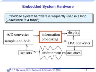
Partial English description System interface “Move the elevator either up or down to reach the requested floor. Once at the requested floor, open the door for at least 10 seconds, and keep it open until the requested floor changes. Ensure the door is never open while moving. Don’t change directions unless there are no higher requests when moving up or no lower requests when moving down…” up Unit Control down open floor Sequential program model req Request Resolver Inputs: int floor; bit b1..bN; up1..upN-1; dn2..dnN; Outputs: bit up, down, open; Global variables: int req; buttons inside elevator b1 b2 ... void UnitControl() { up = down = 0; open = 1; while (1) { while (req == floor); open = 0; if (req > floor) { up = 1;} else {down = 1;} while (req != floor); up = down = 0; open = 1; delay(10); } } void RequestResolver() { while (1) ... req = ... ... } bN up1 up/down buttons on each floor up2 dn2 up3 dn3 void main() { Call concurrently: UnitControl() and RequestResolver() } ... dnN Elevator controller using a sequential program model You might have come up with something having even more if statements.
Finite-state machine (FSM) model • Trying to capture this behavior as sequential program is a bit awkward • Instead, we might consider an FSM model, describing the system as: • Possible states • E.g., Idle, GoingUp, GoingDn, DoorOpen • Possible transitions from one state to another based on input • E.g., req > floor • Actions that occur in each state • E.g., In the GoingUp state, u,d,o,t = 1,0,0,0 (up = 1, down, open, and timer_start = 0) • Try it...
req > floor u,d,o, t = 1,0,0,0 GoingUp !(req > floor) timer < 10 req > floor !(timer < 10) u,d,o,t = 0,0,1,0 UnitControl process using a state machine Idle DoorOpen u,d,o,t = 0,0,1,1 req == floor req < floor !(req<floor) u,d,o,t = 0,1,0,0 GoingDn u is up, d is down, o is open req < floor t is timer_start Finite-state machine (FSM) model
Formal definition • An FSM is a 6-tuple F<S, I, O, F, H, s0> • S is a set of all states {s0, s1, …, sl} • I is a set of inputs {i0, i1, …, im} • O is a set of outputs {o0, o1, …, on} • F is a next-state function (S x I→ S) • H is an output function (S → O) • s0is an initial state • Moore-type • Associates outputs with states (as given above, H maps S → O) • Mealy-type • Associates outputs with transitions (H maps S x I→ O) • Shorthand notations to simplify descriptions • Implicitly assign 0 to all unassigned outputs in a state • Implicitly AND every transition condition with clock edge (FSM is synchronous)
We described UnitControl as an FSMD req > floor u,d,o, t = 1,0,0,0 GoingUp !(req > floor) timer < 10 req > floor !(timer < 10) u,d,o,t = 0,0,1,0 Idle DoorOpen u,d,o,t = 0,0,1,1 req == floor req < floor !(req<floor) u,d,o,t = 0,1,0,0 GoingDn u is up, d is down, o is open req < floor t is timer_start Finite-state machine with datapath model (FSMD) • FSMD extends FSM: complex data types and variables for storing data • FSMs use only Boolean data types and operations, no variables • FSMD: 7-tuple <S, I , O, V, F, H, s0> • S is a set of states {s0, s1, …, sl} • I is a set of inputs {i0, i1, …, im} • O is a set of outputs {o0, o1, …, on} • V is a set of variables {v0, v1, …, vn} • F is a next-state function (S x I x V→ S) • H is an action function (S → O + V) • s0 is an initial state • I,O,V may represent complex data types • (i.e., integers, floating point, etc.) • F,H may include arithmetic operations • H is an action function, not just an output function • Describes variable updates as well as outputs • Complete system state now consists of current state, si, and values of all variables
req > floor u,d,o, t = 1,0,0,0 GoingUp !(req > floor) timer < 10 req > floor u,d,o,t = 0,0,1,0 !(timer < 10) Idle DoorOpen u,d,o,t = 0,0,1,1 req == floor req < floor !(req<floor) u,d,o,t = 0,1,0,0 GoingDn req < floor Describing a system as a state machine • 2. Declare all variables (none in this example) 1. List all possible states • 3. For each state, list possible transitions, with conditions, to other states • 4. For each state and/or transition, list associated actions • 5. For each state, ensure exclusive and complete exiting transition conditions • No two exiting conditions can be true at same time • Otherwise nondeterministic state machine • One condition must be true at any given time • Reducing explicit transitions should be avoided when first learning u is up, d is down, o is open t is timer_start
State machine vs. sequential program model • Different thought process used with each model • State machine: • Encourages designer to think of all possible states and transitions among states based on all possible input conditions • Sequential program model: • Designed to transform data through series of instructions that may be iterated and conditionally executed • State machine description excels in many cases • More natural means of computing in those cases • Not due to graphical representation (state diagram) • Would still have same benefits if textual language used (i.e., state table) • Besides, sequential program model could use graphical representation (i.e., flowchart)
Try Capturing Other Behaviors with an FSM • E.g., Answering machine blinking light when there are messages • E.g., A simple telephone answering machine that answers after 4 rings when activated • E.g., A simple crosswalk traffic control light • Others
Capturing state machines in sequential programming language • Despite benefits of state machine model, most popular development tools use sequential programming language • C, C++, Java, Ada, VHDL, Verilog, etc. • Development tools are complex and expensive, therefore not easy to adapt or replace • Must protect investment • Two approaches to capturing state machine model with sequential programming language • Front-end tool approach • Additional tool installed to support state machine language • Graphical and/or textual state machine languages • May support graphical simulation • Automatically generate code in sequential programming language that is input to main development tool • Drawback: must support additional tool (licensing costs, upgrades, training, etc.) • Language subset approach • E.g. using C...
Language subset approach • Follow rules (template) for capturing state machine constructs in equivalent sequential language constructs • Used with software (e.g.,C). Similar in hardware languages (e.g.,VHDL or Verilog) • Capturing UnitControl state machine in C • Enumerate all states (#define) • Declare state variable initialized to initial state (IDLE) • Single switch statement branches to current state’s case • Each case has actions • up, down, open, timer_start • Each case checks transition conditions to determine next state • if(…) {state = …;} #define IDLE0 #define GOINGUP1 #define GOINGDN2 #define DOOROPEN3 void UnitControl() { int state = IDLE; while (1) { switch (state) { IDLE: up=0; down=0; open=1; timer_start=0; if (req==floor) {state = IDLE;} if (req > floor) {state = GOINGUP;} if (req < floor) {state = GOINGDN;} break; GOINGUP: up=1; down=0; open=0; timer_start=0; if (req > floor) {state = GOINGUP;} if (!(req>floor)) {state = DOOROPEN;} break; GOINGDN: up=1; down=0; open=0; timer_start=0; if (req < floor) {state = GOINGDN;} if (!(req<floor)) {state = DOOROPEN;} break; DOOROPEN: up=0; down=0; open=1; timer_start=1; if (timer < 10) {state = DOOROPEN;} if (!(timer<10)){state = IDLE;} break; } } } UnitControl state machine in sequential programming language
General template #define S0 0 #define S1 1 ... #define SN N void StateMachine() { int state = S0; // or whatever is the initial state. while (1) { switch (state) { S0: // Insert S0’s actions here & Insert transitions Ti leaving S0: if( T0’s condition is true ) {state = T0’s next state; /*actions*/ } if( T1’s condition is true ) {state = T1’s next state; /*actions*/ } ... if( Tm’s condition is true ) {state = Tm’s next state; /*actions*/ } break; S1: // Insert S1’s actions here // Insert transitions Ti leaving S1 break; ... SN: // Insert SN’s actions here // Insert transitions Ti leaving SN break; } } }
Without hierarchy With hierarchy A1 z A w x A1 z y B x y B A2 w z A2 Concurrency B C D C1 D1 x u y v C2 D2 HCFSM and the Statecharts language • Hierarchical/concurrent state machine model (HCFSM) • Extension to state machine model to support hierarchy and concurrency • States can be decomposed into another state machine • With hierarchy has identical functionality as Without hierarchy, but has one less transition (z) • Known as OR-decomposition • States can execute concurrently • Known as AND-decomposition • Statecharts • Graphical language to capture HCFSM • timeout:transition with time limit as condition • history: remember last substate OR-decomposed state A was in before transitioning to another state B • Return to saved substate of A when returning from B instead of initial state
fire fire fire FireGoingDn u,d,o = 0,1,0 ElevatorController fire u,d,o = 0,0,1 floor==1 floor>1 FireDrOpen With hierarchy !fire fire UnitControl RequestResolver UnitControl NormalMode req>floor NormalMode u,d,o = 1,0,0 GoingUp !(req>floor) req>floor ... u,d,o = 0,0,1 u,d,o = 0,0,1 Idle DoorOpen timeout(10) req==floor !fire fire req<floor !(req>floor) u,d,o = 0,1,0 GoingDn req<floor FireMode FireMode fire FireGoingDn u,d,o = 0,1,0 !fire u,d,o = 0,0,1 floor==1 floor>1 FireDrOpen With concurrent RequestResolver fire UnitControl with FireMode req>floor UnitControl • FireMode • When fire is true, move elevator to 1st floor and open door u,d,o = 1,0,0 GoingUp !(req>floor) req>floor • w/o hierarchy: Getting messy! u,d,o = 0,0,1 timeout(10) u,d,o = 0,0,1 Idle DoorOpen req==floor • w/ hierarchy: Simple! req<floor !(req<floor) u,d,o = 0,1,0 GoingDn req<floor Without hierarchy
ElevatorController int req; UnitControl RequestResolver NormalMode up = down = 0; open = 1; while (1) { while (req == floor); open = 0; if (req > floor) { up = 1;} else {down = 1;} while (req != floor); open = 1; delay(10); } } ... req = ... ... !fire fire FireMode up = 0; down = 1; open = 0; while (floor > 1); up = 0; down = 0; open = 1; Program-state machine model (PSM): HCFSM plus sequential program model • Program-state’s actions can be FSM or sequential program • Designer can choose most appropriate • Stricter hierarchy than HCFSM used in Statecharts • transition between sibling states only, single entry • Program-state may “complete” • Reaches end of sequential program code, OR • FSM transition to special complete substate • PSM has 2 types of transitions • Transition-immediately (TI): taken regardless of source program-state • Transition-on-completion (TOC): taken only if condition is true AND source program-state is complete • SpecCharts: extension of VHDL to capture PSM model • SpecC: extension of C to capture PSM model • NormalMode and FireMode described as sequential programs • Black square originating within FireMode indicates !fire is a TOC transition • Transition from FireMode to NormalMode only after FireMode completed