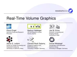
Real-Time Volume Graphics
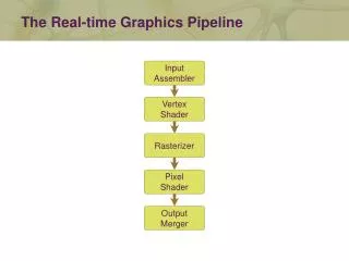
Real-Time Volume Graphics. Pre-Integration and High-Quality Filtering. This is what we want …. But often this is what we get …. Framebuffer. Filtering. Classification. Shading. Integration. Sampling. Volume Rendering Artifacts. Volume Rendering Pipeline Where are errors introduced ?.


Real-Time Volume Graphics
E N D
Presentation Transcript
Framebuffer Filtering Classification Shading Integration Sampling Volume Rendering Artifacts • Volume Rendering Pipeline • Where are errors introduced ? Linear filtering 8 bit blending Low sampling rate High frequencies Quantized Gradients
284 Samples 128 Samples Sampling Artifacts • Reason: • Low sampling rate • Solutions: • Increase sampling rate to Nyquist frequency => at least 2 samples per voxel • Adaptive Sampling • Higher sampling rate where data contains high frequencies
Sampling Artifacts • Remove woodgrain artifact by stochastic jittering of ray-start position • Look-up noise texture to offset ray-position in view direction
Filtering Artifacts • 643 volume, object-aligned slices bi-cubic filter bi-linear filter
Filtering Artifacts • Reason: • Internal filtering precision dependent on input texture format • Linear filters do not approximate the ideal reconstruction filter (sinc-Filter) very well • Solutions: • Use internal format with higher precision • Implement a HQ filter in a fragment program
Discretized version of convolution integral Filtering Artifacts / HQ-Filters filter convolution discrete signal h(x) f[x] g(x) = f[x] * h(x) Filter width: 2m
Filtering Artifacts / HQ-Filters • Procedural evaluation of kernel and convolution • Texture-based kernel and convolution FetchInputSamples();ComputeWeights_X();for (i=0; i<3; i++) Convolution_X();ComputeWeights_Y();Convolution_Y(); pre-sampled B-spline kernelfrom [Hadwiger et al. 2001] see for example NVIDIA’sBicubicTexMagnification demo
Filtering Artifacts / HQ-Filters • Procedural evaluation of kernel and convolution • Texture-based kernel and convolution FetchInputSamples();ComputeWeights_X();for (i=0; i<3; i++) Convolution_X();ComputeWeights_Y();Convolution_Y(); R G B A t0 t1 t2 t3 pre-sampled B-spline kernelfrom [Hadwiger et al. 2001] see for example NVIDIA’sBicubicTexMagnification demo
Transform original kernel into look-up texture Replicate kernel tile over output grid Filtering Artifacts / HQ-Filters kernel tile
Easy when kernel separable Use same 1D kernel tile for all axes Sample two (or three) timesand multiply weights Separable bi-cubic andtri-cubic filters need onlyone 1D RGBA kernel tile Filtering Artifacts / HQ-Filters
Filtering Artifacts / HQ-Filters • Distribution instead of gathering • Works for all filter shapes and sizes • Works for separable and non-separable kernels • Multi-pass evaluation of filter convolution sum
Tri-cubic gradients and second derivatives for isosurfaces possible in real-time! Filtering Artifacts / HQ-Filters
Filtering Artifacts / HQ-Filters linear cubic
Filtering Artifacts / HQ-Filters linear cubic
Classification Artifacts Pre-Classification Filtering Classification … … Post-Classification Filtering Classification … … Pre-Integrated-Classification Pre-Integration Filtering Integral Lookup … …
T(s) T(s(x)) s Classification Artifacts • High frequencies in the transfer function T increase required sampling rate s(x) x x
50 x more slices Classification Artifacts multiple peaks T(s) s
Classification Artifacts / Pre-integration • Reason: • Classification can add high frequencies to rendered data • Solution: • Pre-Integrated Classification=> split numerical integration into • one pre-integration for the TF • one integration for the scalar field • slab-by-slabrendering
Classification Artifacts / Pre-integration slice-by-slice slab-by-slab image-order sample-by-sample raySegment-by-raySegment object-order
Eye Classification Artifacts / Pre-integration Slab Screen sb sf
Pre-Integration of all possible combinations save values In table sf sb sb sf Classification Artifacts / Pre-integration • Pre-processing
Classification Artifacts / Pre-integration • Rendering project back slice sf sb front slice back slice
Classification Artifacts / Pre-integration // define inputs from application struct appin { float4 Position : POSITION; float4 Normal : NORMAL; float4 TCoords0 : TEXCOORD0; }; // define outputs from vertex shader struct vertout { float4 HPosition : POSITION; float4 TCoords0 : TEXCOORD0; float4 TCoords1 : TEXCOORD1; }; vertout main(appin IN, uniform float4x4 ModelViewProj,// model-view-projection matrix uniform float4x4 ModelViewI, // inverse of the modelview matrix uniform float4x4 TexMatrix, //Texture matrix for texture 0 uniform float SamplingDistance ) Cg Vertex Program
Classification Artifacts / Pre-integration { vertout OUT; OUT.TCoords0 = mul(TexMatrix, IN.TCoords0); // transform view pos vec and view dir to obj space float4 vPosition = mul(ModelViewI, float4(0,0,0,1)); float4 vDir = normalize(mul(ModelViewI, float4(0.f,0.f,-1.f,1.f))); //compute position of virtual back vertex float4 eyeToVert = normalize(IN.Position - vPosition); float4 backVert = {1,1,1,1}; backVert = IN.Position - eyeToVert * (SamplingDistance /dot(vDir,eyeToVert)); //compute texture coordinates for virtual back vertex OUT.TCoords1 = mul(TexMatrix, backVert); // transform vertex position into homogenous clip-space OUT.HPosition = mul(ModelViewProj, IN.Position); return OUT; } Cg Vertex Program
utilize sf and sb as texture coordinates for the dependent texture sb sf Classification Artifacts / Pre-integration • Rendering fetch sf and sb during rasterization sf sb slice
fetch pre-integrated ray-segment sb sf • Rendering texture polygon with pre-integrated value sf sb slice
Classification Artifacts / Pre-integration struct v2f_simple { float4 Hposition : POSITION; float3 TexCoord0 : TEXCOORD0; float3 TexCoord1 : TEXCOORD1; float4 Color0 : COLOR0; }; float4 main(v2f_simple IN, uniform sampler3D Volume, uniform sampler2D TransferFunction, uniform sampler2D PreIntegrationTable) : COLOR { float4 lookup; //sample front scalar lookup.x = tex3D(Volume, IN.TexCoord0.xyz).x; //sample back scalar lookup.y = tex3D(Volume, IN.TexCoord1.xyz).x; //lookup and return pre-integrated value return tex2D(PreIntegrationTable, lookup.yx); } Cg Fragment Program
Classification Artifacts / Pre-integration • Pre-integration table to large • 12bit x 12bit x RGBA8 = 4096x4096x32bit = 64MB • Pre-integration table to slow to compute • even with integral functions • Solution: • use Integral functions • Store integral functions in 1D floating point texture • two 1D table lookups
Classification Artifacts / Pre-integration • Almost no performance penalty in sw raycasting • Cache last scalar value • Currently slower on graphics hardware • Temporary fragment registers are zeroed • Two lookups into the volume per fragment => multiple integration steps @ once (raycasting) • Pre-integrated volume rendering still not “correct” • Assumes linear progression of scalar value along ray=> Gaussian Transfer Functions (Kniss Vis’03)
128 slices pre-classification 128 slices post-classification 284 slices post-classification 128 slices pre-integrated Classification Artifacts / Pre-integration
Classification Artifacts / Pre-integration single step
Classification Artifacts / Pre-integration multiple peaks
Classification Artifacts / Pre-integration many peaks
Classification Artifacts / Pre-integration acoustic volume inside car cabine
Classification Artifacts / Pre-integration inhomogeneous region homogeneous region
Shading Artifacts • Reasons: • Gradients are pre-computed and quantized • Interpolation of normals causes unnormalized normals • Solutions: • Store gradients in high-precision texture,re-normalize in fragment program too much memory • Compute gradients on-the-fly high-quality gradient • many texture fetches • Sobel gradient
Shading Artifacts • Add offset to texture coordinate of fragment // samples for forward differences half3 normal; half3 sample1; sample1.x = (half)tex3D(Volume, IN.TexCoord0+offset.xwww).x; sample1.y = (half)tex3D(Volume, IN.TexCoord0+offset.wyww).x; sample1.z = (half)tex3D(Volume, IN.TexCoord0+offset.wwzw).x; // additional samples for central differences half3 sample2; sample2.x = (half)tex3D(Volume, IN.TexCoord0-offset.xwww).x; sample2.y = (half)tex3D(Volume, IN.TexCoord0-offset.wyww).x; sample2.z = (half)tex3D(Volume, IN.TexCoord0-offset.wwzw).x; // compute central differences gradient normal = normalize(sample2.xyz – sample1.xyz); Cg Fragment Program
Shading Artifacts • Pass in shifted texture coordinates // samples for forward differences half3 normal; half3 sample1; sample1.x = (half)tex3D(Volume, IN.TexCoord2).x; sample1.y = (half)tex3D(Volume, IN.TexCoord4).x; sample1.z = (half)tex3D(Volume, IN.TexCoord6).x; // additional samples for central differences half3 sample2; sample2.x = (half)tex3D(Volume, IN.TexCoord3).x; sample2.y = (half)tex3D(Volume, IN.TexCoord5).x; sample2.z = (half)tex3D(Volume, IN.TexCoord7).x; // compute central differences gradient normal = normalize(sample2.xyz – sample1.xyz); Cg Fragment Program
Blending Artifacts 16 bit floating point blending 32 bit floating point blending 8 bit fixed point blending
Blending Artifacts • Reason: • 8 bit blending accumulates error in the framebuffer • Solutions: • Blending into a floating point pbuffer • Nv4x support 16 bit floating point blending • Nv3x, R3xx and R4xx do not support floating point blending=> implement blending in a fragment program • Ping-pong blending to prevent read/write race conditions
Blending Artifacts • The graphics hardware does not support floating point blending (NV3x, R3xx, R4xx)=> implement blending yourself • Clean: ping-pong Blend A B
Blending Artifacts • The graphics hardware does not support floating point blending (NV3x, R3xx, R4xx)=> implement blending yourself • Clean: ping-pong Blend A B
Blending Artifacts • The graphics hardware does not support floating point blending (NV3x, R3xx, R4xx)=> implement blending yourself • Clean: ping-pong Blend A B
Blending Artifacts • The graphics hardware does not support floating point blending (NV3x, R3xx, R4xx)=> implement blending yourself • Dirty: ping without the pong Blend A B

![Real-Time Volume Graphics [03] GPU-Based Volume Rendering](https://cdn2.slideserve.com/4026797/real-time-volume-graphics-03-gpu-based-volume-rendering-dt.jpg)
![Real-Time Volume Graphics [07] Global Volume Illumination](https://cdn2.slideserve.com/4312752/real-time-volume-graphics-07-global-volume-illumination-dt.jpg)
![Real-Time Volume Graphics [06] Local Volume Illumination](https://cdn2.slideserve.com/4770316/real-time-volume-graphics-06-local-volume-illumination-dt.jpg)
![Real-Time Volume Graphics [05] Transfer Functions](https://cdn2.slideserve.com/5136640/real-time-volume-graphics-05-transfer-functions-dt.jpg)
![Real-Time Volume Graphics [02] GPU Programming](https://cdn3.slideserve.com/6316608/real-time-volume-graphics-02-gpu-programming-dt.jpg)