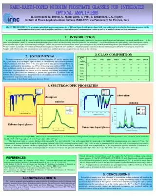
EDFA Optical Amplifiers
Erbium Doped Fiber Amplifiers José Ferreira da Rocha, Mário Lima University of Aveiro frocha@det.ua.pt, mlima@det.ua.pt. EDFA Optical Amplifiers.

EDFA Optical Amplifiers
E N D
Presentation Transcript
Erbium Doped Fiber AmplifiersJosé Ferreira da Rocha, Mário LimaUniversity of Aveirofrocha@det.ua.pt, mlima@det.ua.pt
EDFA Optical Amplifiers • Erbium Doped Fiber Amplifier (EDFA): is the most deployed fiber amplifier as its amplification window coincides with the third transmission window (1530nm – 1570nm) of silica-based optical fiber • Implementation: Pump laser (980nm, 1480 nm), isolators E1- 2b Optical technologies
EDFA Optical Amplifiers • Based on excitation of Er3+ ions of the EDF http://www.tlc.unipr.it/bononi/ricerca/edfa.html Emmanuel Desurvire, "Eribum- Doped fiber amplifiers: principles ans application", John Wiley & Sons, Inc., New York, 1994) E1- 2b Optical technologies
DOPED FIBER AMPLIFIERS - PRINCIPLE In doped fiber amplifiers (DFA), the fiber core is doped with rare earth ions: erbium, neodymium, ytterbium, holmium, thulium. The ions constitute the active medium through which optical gain is obtained. When optically pumped, these ions are excited to an higher energy state. When simulated by incoming photons the ions emit photons Optical gain. In accordance with the type of ion used, DFAs can be used in a broad spectral range: from the visible part to the infrared region of the spectrum. E1- 2b Optical technologies
l = 1550 nm Signal in (to be amplified) WC Signal out (Amplified) ISOLATOR ISOLATOR Doped fiber (Erbium, Neodemium, Thulium, etc) l = 1550 nm Termination Pump laser diode l DOPED FIBER AMPLIFIERS - STRUCTURE It may be necessary to reject remaining pump power at the DFA output with an optical filter. E1- 2b Optical technologies
DOPED FIBER AMPLIFIERS - STRUCTURE If the pump power is not enough and/or the fiber is too long, the device can act as an attenuator. Too strong pump power and/or short fiber, leads to inefficient use of pump power. Conclusion: for each situation the fiber length must be optimized. E1- 2b Optical technologies
l = 1550 nm ISOLATOR ISOLATOR WC WC Signal in Signal out l l = 1550 nm Pump laser diode Pump laser diode Termination Termination l l = 980 nm = 980 nm ERBIUM DOPED FIBER AMPLIFIER (EDFA)- z The first commercial EDFAs were available in 1990. Practical amplifiers use a range of values from a few meters of fiber with erbium doping levels around 1000 ppm, to hundreds of meters of fiber and doping concentration lower than 100 ppm. Optional E1- 2b Optical technologies
WC Signal in Signal out ISOLATOR ISOLATOR l l l l l = 1550 nm = 1550 nm = 1550 nm = 1550 nm = 1550 nm Termination Pump laser diode l ISOLATOR Signal in ISOLATOR WC Signal out Termination ISOLATOR ISOLATOR WC WC Signal in Signal out l l = 1550 nm Pump laser diode Pump laser diode Termination Termination l l = 980 nm = 980 nm Fiber Optic Transmission Bandwidth: EDFA Amplifiers PRE AMP Components Inside an Er-Doped Amplifier Isolator To avoid backward ASE WDM coupler To couple the input signal and the pumps inside the Er-Doped Fiber Monitoring output ports To have a monitor to control the power = 980 nm BOOST AMP BOOST/LINE AMP E1- 2b Optical technologies
Remote Pumping For example, for submarine systems, remote pumping can be used in order not to have to electrically feed the amplifiers and remove electronic parts. Nowadays, this is used in pumping up to 200km E1- 2b Optical technologies IBM WhiteBook, pag.172
Pumping To maintain carrier inversion, other types of pumping can be used Bigger nucleus, therefore bigger power, easier coupling of multiple pumps Lesser non-linear effects on the signal E1- 2b Optical technologies IBM White Book, pags.168-170
Erbium Doped Fiber Amplifier EDFA Erbium emission band fits the minimum fiber loss. EDFA’s allows re-amplification of DWDM signals in the C- and L-band. E1- 2b Optical technologies
EDFA – Effects on the signal Input spectrum Noise ASE Output spectrum E1- 2b Optical technologies
EDFA - example of saturation E1- 2b Optical technologies
PUMPING Pumping possible at 532, 670 807, 980, 1480 nm. Energy levels area broadened when erbium ions are doped into silica fiber. E1- 2b Optical technologies
PUMPING First experiments used high power pumps, in the visible part of the electromagnetic spectrum (argon ion, Nd:YAG, dye lasers) These pumps lead to inefficient and bulky amplifiers. More practical structures use semiconductor pump lasers (820, 980 or 1480 nm). E1- 2b Optical technologies
PUMPING AT 807 nm The first semiconductor pump worked at 807 nm, due to availability of high power AlGaAs lasers. E1- 2b Optical technologies
THREE-LEVEL SYSTEM AT 807 nm Erbium ions are pumped from the ground state (4I15/2) to a higher sate (4I9/2) . The excited ions relax rapidly (approx. 1 microsec) to a lower energy state (4I9/2 to 4I13/2) The fluorescence decay time of state 4I13/2 is relatively high (approximately 14 ms). The fast decay from 4I9/2 to 4I13/2, together with long decay time from 4I13/2 to 4I15/2 originate an almost ideal three-level system. So population inversion can occur between 4I13/2 and 4I15/2 states. E1- 2b Optical technologies
AMPLIFICATION AT 807 nm With appropriate pump power, population inversion occurs between states 4I13/2 and 4I15/2(condition for stimulated emission). An incident photon can stimulate the transition from sate 4I13/2 to 4I15/2, with emission of another photon. This is amplification of the incident signal. E1- 2b Optical technologies
As the population in excited state 4I13/2 increases The so called excited-state absorption (ESA) also increases ESA – Additional absorption of pump photons (807 nm), inducing transitions from 4I13/2 to 2H11/2 ESA causes low pumping efficiency at 807 nm ESA AT 807 nm E1- 2b Optical technologies
PUMPING AT 807 nm Pumping efficiencies of 0.8 dB/mW can be obtained at 820 nm This value is about an order of magnitude lower than the values obtainable at 980 and 1480 nm (11 dB/mW A 980 nm). However gains of 30 dB achievable with pumping powers of 40 to 50 mW. These are easily obtained with AlGaAs semiconductor lasers. The pump power can be reduced by using silica fibers doped with aluminum and phosphorous or by using fluorophosphate fibers. E1- 2b Optical technologies
PUMPING AT 980 AND 1480 nm Pumping at 980 E 1480 nm is not affected by ESA. More efficient than at 807 nm. • This has originated the development of semiconductor lasers with emission spectra in the range 980 to 1480 nm. • With this pumps it is possible to obtain high gains (30-40 dB) with just a few mW of pumping power. E1- 2b Optical technologies
PUMPING AT 980 nm Advantages The most efficient of the three cases (807, 980 and 1480 nm). Due to the absence of ESA and also to the greater value of the ground-state absorption cross-section. This means that pumping at 980 nm needs less power. Slope efficiencies (D gain/ D pump power) of 11 dB/mW can be obtained at 980 nm. This pumping wavelength produces also less amplified spontaneous emission (ASE) noise. More on this later. E1- 2b Optical technologies
PUMPING AT 980 nm Disadvantages A variation of just ± 0.5 nm in the pump wavelength can degrade the slope efficiency in about 10%. This narrow range of useful wavelengths is due to the restricted values of possible energy differences between levels 4I15/2 and 4I11/2. As a consequence of the previous property, monomode pump lasers must be used for high efficiencies. And the pump operating temperature must be tightly controlled, to avoid pump wavelength drift. The same applies to 807 nm pumping. For an optimum performance, the EDFA fiber must be monomode both for the signal to be amplified (1520-1520 nm wavelength range) and the pump (980 nm). This is difficult to achieve for such a big wavelength range. The situation is even worse for 807 nm pumping. E1- 2b Optical technologies
PUMPING AT 980 nm Example A gain of 33 dB has been obtained for a commercial amplifier with: • Pump power: 10 mW • Pump laser current: 80 mA • Total electrical power for the whole amplifier module: 175 mW E1- 2b Optical technologies
PUMPING AT 1480 nm Advantages The wide range of possible energy differences between levels 4I15/2 and 4I13/2 originates a corresponding wide range (50 nm) of useful pump wavelengths. As a consequence of the previous property, cheaper multimode pump lasers (with spectral widths of several nm) can be used with good amplifier efficiencies. Resulting also from the first property, the tolerance relative to the pump central wavelength is also higher. Consequently it is not necessary to control the pump operating temperature as tightly as for 980 nm pumping . E1- 2b Optical technologies
PUMPING AT 1480 nm Advantages Due to the proximity of their wavelengths, it is easier to achieve monomode operation for both signal and pump. This is a much better situation compared with 807 and 980 nm pumping, and it is important to obtain good overlapping of both fields within the fiber core. E1- 2b Optical technologies
PUMPING AT 1480 nm Disadvantages Due to the proximity of pumping and stimulated emission levels it is more difficult to achieve population inversion, compared to pumping at 980 nm. As a consequence of the previous property, pump powers at 1480 nm must be higher compared to pumping at 980 nm. Also due to incomplete population inversion this pumping wavelength originates higher levels of amplified spontaneous emission (ASE) noise. More on this later. E1- 2b Optical technologies
PUMPING AT 1480 nm Example Gains of 47 dB have been obtained with pump powers of 133 mW. E1- 2b Optical technologies
GAIN The gain of an EDFA is given by: From the gain factor expression: E1- 2b Optical technologies
GAIN For a given fiber length, the gain starts by increasing exponentially with pump power. After a certain pump power value the increase is lower than the exponential law and approaches a constant value. Explanation: Initially (low pump powers) as the pump power increases more erbium ions are excited and the gain increases. For high pump powers almost all available erbium ions are excited along the whole fiber length. Then further pump power increments don’t change the situation. The gain is kept almost constant. Gain (dB) Gain (dB) Amplifier length (m) Pump Power (mW) Agrawal, G. P., “Fiber-Optic Communication Systems”, 1992: John Wiley E1- 2b Optical technologies
GAIN For a given pump power, the gain starts by increasing with fiber length. Then it reaches a maximum value for a given fiber length (optimum value) and beyond this value the gain decreases rapidly. Explanation: For a big fiber length the pump power is not enough to pump the final part of the amplifier. This part absorbs signal photons instead of emitting stimulated photons (the amplifying mechanism) and the gain decreases. Conclusion: The fiber length must be optimized carefully for each value of pump power. Gain (dB) Gain (dB) Amplifier length (m) Pump Power (mW) Agrawal, G. P., “Fiber-Optic Communication Systems”, 1992: John Wiley E1- 2b Optical technologies
EDFA - Gain Optical Amplifiers (OA), amplify incident light through stimulated emission, as in the LASER system but without the feedback. The core of an OA is the Gain obtained when the system is optically or electrically pumped. Saturation power the “small signal gain equation” in the unsaturated region is the gain factor G is equal to: Unsaturated value of the G factor Keiser Gerd, “ Optical Fiber Communications”, McGraw-Hill,2000 E1- 2b Optical technologies
EDFA – Working Principle The small signal gain is considered not saturated nor level depleted (dB) E1- 2b Optical technologies
BANDWIDTH The spectral width of the 1536 nm transition in Erbium ions is limited. However when hosted in the fiber glass, this spectral width increases due the perturbation of the ions by the host glass. As a result, 3 dB bandwidths of 10 nm can easily be achieved by EDFAs of silica fiber doped with germanium. The EDFA bandwidth can be further increased, specially at higher wavelengths, by the introduction of alumina in the fiber core. E1- 2b Optical technologies
BANDWIDTH Example of a gain curve E1- 2b Optical technologies
GAIN SATURATION For high values of output power the gain decreases with signal power (gain saturation). • Gain saturation can contribute to the distortion of optical pulses being amplified. More on this later. E1- 2b Optical technologies
EDFA- typical gain curve E1- 2b Optical technologies
P λ Fiber Optic Transmission Bandwidth: EDFA Amplifiers Issues in the WDM systems: Gain Flattening The amplification bandwidth must be “flat” along all the amplification range to have the same behavior for all the wavelengths. Passive Equalization Active Equalization Gain Transient Avoid the fluctuations on the WDM channels due to the add and drop of part of these channels along the optical path E1- 2b Optical technologies
Problems from EDFA cascading Since the gain is wavelength dependent, at the end of an amplifier cascade, problems can be appear However, if the amplifier is operated on the saturation, or the gain is equalized through a different method, then the problem is solved E1- 2b Optical technologies IBM WhiteBook, pag. 163
Equalizing the EDFA gain Saturation Operation A laser component is Introduced in the gain spectrum • through ASE realimentation or through laser Introduction of an Optical Filter • The noise figure is increased Introduction of new dopants Manipulating the guides doping way Controlling the fiber dimensions and pump power ... At a system level, preemphasis can be done E1- 2b Optical technologies
EDFA – Characterization ASE optical power (mW) Pumped signal optical power(mW) E1- 2b Optical technologies
Second Operation Window (1600nm) A gain can be achieved on the second window by: • doping with other dopants (Al, P, etc) • using longer fiber length with lesser inversion Ivan Kamaninov, T. Li, “Optical Fiber Telecommunications, IVA – Components”, Academic Press, 2002. E1- 2b Optical technologies
RATE EQUATIONS We can use a three-level model to derive the EDFA rate equations. To account for the excited sate absorption (ESA) a four-level is needed. For our cases there is no ESA (980 and 1480 nm pumping). Furthermore, for 980 nm pumping level 3 is almost empty so a two-level model gives good approximations. E1- 2b Optical technologies
RATE EQUATIONS If we consider just the stimulated emission (transition from level 2 to level 1) and absorption of signal photons (transition from level 1 to level 2) we have: E1- 2b Optical technologies
RATE EQUATIONS Interpretation of factor Characterizes the capacity of a given active material (erbium ions) to generate stimulated processes. Is the flow of signal photons per unit area, that is, the number o photons that crosses the unit of cross-section area per unit time. The transition probability Ws must be proportional to this term, since the larger the photon flux the is the probability of stimulated transitions. E1- 2b Optical technologies
RATE EQUATIONS Interpretation of the equation Variation of population concentration in level 2, per time unit. Term corresponding to the stimulated emission (transition 2-1). This term must be proportional to the stimulated transition probability (Ws) and to the population concentration in state 2 (N2). This term is negative since the stimulated emission corresponds to a decrease of ions in state 2 (dN2/dt<0). E1- 2b Optical technologies
RATE EQUATIONS Interpretation of the equation Term corresponding to the stimulated absorption (transition 1-2). This term must be proportional to the stimulated transition probability (Ws) and to the population concentration in state 1 (N1). This term is positive since the absorption corresponds to an increase of ions in state 2 (dN2/dt>0). E1- 2b Optical technologies
RATE EQUATIONS If we consider just the spontaneous emission of photons (transition from level 2 to level 1) we have: E1- 2b Optical technologies
RATE EQUATIONS Considering finally the absorption of the pump photons together with all the terms considered previously, we obtain the rate equation: Transitions from level 1 to level 3 and then rapidly to state 2, by absorption of pump photons. E1- 2b Optical technologies
RATE EQUATIONS Considering now the population in state 1 (N1) we have all the terms considered previously, but with signs changed (when the population in level 2 increases, the population in level 1 decreases and vice-versa): E1- 2b Optical technologies