Operational Amplifiers
Operational Amplifiers. Hunter Greene Wendy Siemens 20 February 2006. Operational Amplifier. Outline Introduction Characteristics Idealizations Cautions Applications References. V +. V -. Introduction. Performs operations on input voltages Active component V+ and V- power


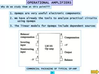
Operational Amplifiers
E N D
Presentation Transcript
Operational Amplifiers Hunter Greene Wendy Siemens 20 February 2006
Operational Amplifier • Outline • Introduction • Characteristics • Idealizations • Cautions • Applications • References
V+ V- Introduction • Performs operations on input voltages • Active component • V+ and V- power • Can amplify inputs
V+ V- Characteristics • Symbol • Positive-going input • Negative-going input • Open loop operation: a very small difference between +Vin and -Vin swings the output voltage to the corresponding Vref (V+ or V-)
+15V V1 Vout V2 -15V Characteristics • Open Loop Operation • If V1>V2, Vout=+15V • If V1<V2, Vout=-15V • If V1=V2, Vout=0V • Typical op-amps swing from V+ to V- with mV input voltage differences
Characteristics • Closed Loop Operation • Golden Rule 1: The output attempts to make the input voltage difference zero. • Golden Rule 2: The inputs draw no current.
Characteristics • V+=Vin and V-=V+ • R1/Vin=R2/(Vout-Vin) • Vin/Vout=(R1+R2)/R1 => Non-inverting Amplifier
V+ V1 Vout V2 V- Idealizations • Infinite open loop gain • Infinite bandwidth • Infinite input impedances (zero input current) • Zero output impedance • Zero noise • Zero input offset voltage • Zero temperature dependence
Idealizations http://hyperphysics.phy-astr.gsu.edu/hbase/electronic/opampcon.html#c1
Cautions • Cautions: • Active regions: clipping occurs when the output saturates • Inputs: feedback must be negative for proper operation • Input difference limits: ignoring limits on input differences cause harmful current levels.
Applications • Cheaper than buying a commercial PID controller. • Saves microcontroller processing time
Applications R1 = R2 = RF Vout= -(V1+V2)
Applications Integrator Circuit
Applications • Positions/velocity measurement • The output signal from an accelerometer can be integrated once to give a voltage output proportional to velocity. • This signal can then be integrated again to give a voltage proportional to position. • This can be much cheaper than other position measuring devices such as LVDT’s which can range from $70-$300.
Applications • Microphone/Speaker Amplification • A non-inverting amplifier is typically used to amplify the small signals from microphones before the sound can be processed. • Computer sound systems must amplify the signals from Digital-to-Analog converters before sending the sound signal to the speakers.
References • For further information: • Wikipedia: http://en.wikipedia.org/wiki/Operational_amplifier • The Art of Electronics, Horowitz and Hill • Introduction to Mechatronics and Measurement Systems, Alciatore and Histand • Electrical Engineering, Hambley • ME 3056 and 4053 lab manual appendices show details of op-amp circuits used in data acquisition