Operational Amplifiers
James Kelly Nathan Knight Gustavo Lee. Operational Amplifiers. Presentation Outline. Introduction Characteristics of Ideal and Real Op-Amps Basic Circuits of Op-Amps Applications Exercise. What is an Op-Amp?.


Operational Amplifiers
E N D
Presentation Transcript
James Kelly Nathan Knight Gustavo Lee Operational Amplifiers
Presentation Outline • Introduction • Characteristics of Ideal and Real Op-Amps • Basic Circuits of Op-Amps • Applications • Exercise
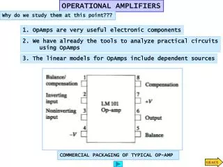
What is an Op-Amp? • An Operational Amplifier (known as an “Op-Amp”) is an integrated circuit that sets an output voltage based on the input voltages provided. • In a circuit, it is used to perform an operation and an amplification where the operation may be add, subtract, filter, integrate, differentiate, etc. • Op-Amps are composed of transistors, resistors, capacitors, and diodes.
Brief History • 1941: Karl Swartzel of Bell Labs developed the first Op-Amp. • Used 3 vacuum tubes, only one input (inverting), and operated on +350 V to achieve 90 dB gain. • 1947: Loebe Julie developed the Op-Amp as it is known today, with two inputs – inverting and non-inverting. • The differential input made a whole range of new functionality possible. • 1953: First commercially available Op-Amp. • George A. Philbrick Researches (GAP-R). GAP-R pioneered the first reasonable-cost, mass-produced operational amplifier • 1961: Advent of solid-state, discrete Op-Amps. • Made possible by the invention of the silicon transistor, which led to the concept of Integrated Circuits (IC) • Reduced power input to ±15V to ±10V • 1962: Op-Amp in a potted module. • Packaging in small black boxes allowed for integration with a circuit
Brief History • 1963: First monolithic IC Op-Amp, the μA702, designed by Bob Widlar at Fairchild Semiconductor. • Monolithic ICs consist of a single chip • 1968: Release of the μA741 • The μA741 became the canonical Op-Amp, from which many modern op-amps base their pinout from, and is still in production today.
Presentation Outline • Introduction • Characteristics of Ideal and Real Op-Amps • Basic Circuits of Op-Amps • Applications • Exercise
Basic Op-Amp (Open-Loop) • : positive power supply • : negative power supply • : non-inverting input terminal • : inverting input terminal • : output terminal • ,,are all referenced to ground
Ideal Op-Amp • Temperature-independent. • The maximum output voltage value is the supply voltage (saturation): • What this means: • Current flow into the op-amp from either input terminal is zero. • Differential voltage between the two input terminals is zero.
Real Op-Amp • Operating temperature range: • Commercial: • Industrial: • Military:
Saturation Vout • Saturation results when the output voltage is equal to the power supply’s voltage • In typical op-amps, the saturation level is about 80% of the supply voltage. • Positive Saturation Cutoff: • Linear Mode: • Negative Saturation Cutoff: Vsat+ Slope = G Vin Vsat- Saturation Cutoff Points
Presentation Outline • Introduction • Characteristics of Ideal and Real Op-Amps • Basic Circuits of Op-Amps • Applications • Exercise
Open Loop vs. Closed Loop • A closed-loop op-amp has feedback from the output back to one of the inputs, whereas an open-loop op-amp does not. Open-Loop Closed-Loop
Negative vs. Positive Feedback • Negative feedback connects the output to the inverting input (-), whereas positive feedback connects the output to the non-inverting input (+). Negative Feedback Positive Feedback
Negative vs. Positive: Output • Negative feedback op-amps can produce any voltage in the supply power range. • Positive feedback op-amps can only produce the maximum and minimum voltages of the range. Vout Vout Vsat+ Vsat+ Vin Vin Vsat- Vsat- Negative Feedback Positive Feedback
Inverting Op-Amp • Functionality: to amplify the input voltage to output voltage with a negative gain.
Non-Inverting Op-Amp • Functionality: to amplify the input voltage to output voltage with a positive gain.
Integrating Op-Amp • Functionality: takes the summation of input voltages over time and provides that as the output signal • =
Derivative Op-Amp • Functionality: takes the rate of change of the inverted input voltage signal and provides that as the output signal
Differential Op-Amp • Functionality: takes the difference between two signals and provides that as the output • If : • Moreover, if :
Summing Op-Amp • Functionality: takes the sum of two or more input voltages and provides an output voltage proportional to the negative of the algebraic sum • If : • Moreover, if : • By setting , the summing op-amp can be used as an averaging operator:
Presentation Outline • Introduction • Characteristics of Ideal and Real Op-Amps • Basic Circuits of Op-Amps • Applications • Exercise
Applications • Active filters • Signal processing • Digital Image processing • Strain gauges • Control circuits • PID controllers for aircraft • PI controllers for temperature measurement circuitry • And much more…
Low-Pass Filter High-Pass Filter • Attenuates frequencies below the cutoff frequency. • Cutoff frequency (Hz): • Gain in the passband: • Attenuates frequencies above the cutoff frequency. • Cutoff frequency (Hz): • Gain in the passband:
Strain Gauge • Strain gauges consist of a pattern of resistive foil mounted on a backing material. • As the foil is subjected to stress, the resistance of the foil changes in a defined way. • This results in an output signal directly related to the stress value, typically a few millivolts. • Op-Amps are utilized to amplify the output signal level to 5~10 V, a suitable level for application to data collection systems.
PID Controller • A proportional-integral-derivative (PID) controller is a generic feedback mechanism widely used in industrial control systems. • It calculates an “error” value as the difference between a measured process variable and a desired setpoint. • Using this error, it calculates a control input using tuning parameters ,,and to drive the error to zero.
PID Controller • So where do op-amps come in? • The error is calculated using a Summing Op-Amp. • Using this error voltage: • The derivative of the error is calculated using a Derivative Op-Amp. • The integral of the error is calculated using an Inverting Op-Amp. • The tuning parameters , , and can be selected by appropriate selection of resistors and capacitors.
And much more… • Comparators • Detectors • Threshold detector • Zero-level detector • Oscillators • Wien bridge oscillator • Relaxation oscillator • Level shifters
Presentation Outline • Introduction • Characteristics of Ideal and Real Op-Amps • Basic Circuits of Op-Amps • Applications • Exercise
Exercise • Consider the circuit above running for 5 seconds. Find when: • , , ,
References • Cetinkunt, Sabri. Mechatronics. Hoboken, NJ: John Wiley & Sons Inc., 2007. • Jung, Walter G. Op Amp Applications Handbook. Analog Devices, Inc., 2005. • “Operational Amplifier.” http://en.wikipedia.org/wiki/Operational_amplifier. • “Operational Amplifier Applications.” http://en.wikipedia.org/wiki/Operational_amplifier_applications. • “The Strain Gauge.” http://web.deu.edu.tr/mechatronics/TUR/strain_gauge.htm. • “The PID Controller.” http://en.wikipedia.org/wiki/PID_controller. • “Feedback in Electronic Circuits: An Introduction.” http://ecee.colorado.edu/~ecen4827/lectures/dm_feedback1.pdf. • “Differentiator and Integrator Circuits” http://www.allaboutcircuits.com/vol_3/chpt_8/11.html. • “Inverting Op-Amp” http://www.wiringdiagrams21.com/2009/12/17/basic-inverting-op-amp-circuit-diagram/
The End • Questions?