Operational Amplifiers
Operational Amplifiers. The operational amplifier, also know as an op amp, is essentially a voltage amplifier with an extremely high voltage gain. One of the building blocks for the construction of analog electronics systems.


Operational Amplifiers
E N D
Presentation Transcript
Operational Amplifiers • The operational amplifier, also know as an op amp, is essentially a voltage amplifier with an extremely high voltage gain. • One of the building blocks for the construction of analog electronics systems. • It may be combined with various external components for a wide variety of purposes.
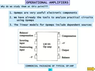
Operational Amplifiers • They are usually fabricated as an integrated circuit, an array of transistors, resistors, and capacitors, on a single silicon chip. • DIP – dual in-line package is the most common package form.
Operational Amplifiers • An ideal amplifier is defined as:
Ideal Operational Amplifiers • An op amp is built as a differential amplifier, where the output voltage is defined as the product of the gain with the voltage difference between of the amplifier’s two inputs. • This means that any stray noise appearing on both inputs are cancelled, and only the voltage difference is amplified.
Ideal Operational Amplifiers • It has two inputs: • v+- the non-inverting input; • v-- the inverting input. • The currents through the inputs are zero, due to fact that an ideal op amp’s has infinite input resistance. • The output voltage given by the open loop gain is defined below:
Negative Feedback • Negative feedback is required to make a large class of useful circuits with op amps. It is achieved when the output voltage, vo , is connected through a network to the inverting input of the op amp.
Negative Feedback • The provision that the open loop gain approaches infinity and negative feedback, allow us to assume that the voltage at the “-” input terminal is driven to to same voltage as that applied at the “+” input terminal.
Closed Loop Gain • The negative feedback connection closes the loop, which allows us to compute the closed-loop gain, AF , for circuits containing such feedback loops.
Power Supply Voltage Constraint • The output voltage of an op amp cannot exceed the supply voltage applied to operate the op amp.
Summary • An ideal op amp with feedback, assumes: • i+= i-= 0 • v-= v+ • Vois bounded by the power supply voltage.
Non-inverting Amplifier • The input of the amplifier is made to the non-inverting input. • The closed loop gain is: • The output is not inverted.
Unity Gain Buffer • The input of the amplifier is made to the non-inverting input. • The closed loop gain is: • The output is not inverted.
Inverting Amplifier • The input of the amplifier is made to the inverting input. • The closed loop gain is: • The output is inverted.
Differential Amplifier • The input of the amplifier is made to both inputs. • The closed loop gain is: • The output is inverted.
Summing Circuit • The input of the amplifier is made to the inverting input. • The closed loop gain is: • The output is inverted.
Integrator Circuit • The input of the amplifier is made to the inverting input. • The closed loop gain is: • The output is inverted.
Active Filters • Filter is a network that is frequency selective. • Passive filters uses only passive components such as: resistors, capacitors, and inductors. • Active filters uses amplifiers to achieve higher performance.
Active Filters • The complex voltage gain is the ratio of the phasor transforms of the output and input voltages.
Current-to-Voltage Converter • Some applications require that a current be converted to a voltage, and this can be accomplished with an op-amp.