Operational Amplifiers
Operational Amplifiers. or Op Amps for short. Objective of Lecture. Describe how an ideal operational amplifier (op amp) behaves. Define voltage gain, current gain, transresistance gain, and transconductance gain.


Operational Amplifiers
E N D
Presentation Transcript
Operational Amplifiers or Op Amps for short
Objective of Lecture • Describe how an ideal operational amplifier (op amp) behaves. • Define voltage gain, current gain, transresistance gain, and transconductance gain. • Explain the operation of an ideal op amp in a voltage comparator and inverting amplifier circuit. • Show the effect of using a real op amp. • Chapters 5.1-5.3 Fundamentals of Electric Circuits
Op Amps Applications • Audio amplifiers • Speakers and microphone circuits in cell phones, computers, mpg players, boom boxes, etc. • Instrumentation amplifiers • Biomedical systems including heart monitors and oxygen sensors. • Power amplifiers • Analog computers • Combination of integrators, differentiators, summing amplifiers, and multipliers
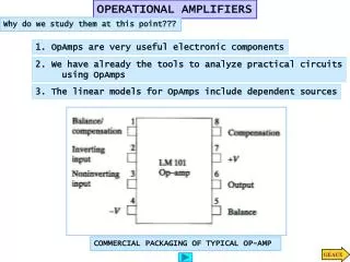
Terminals on an Op Amp Positive power supply (Positive rail) Non-inverting Input terminal Output terminal Inverting input terminal Negative power supply (Negative rail)
Op Amp Equivalent Circuit vd = v2 – v1 A is the open-loop voltage gain v2 v1 Voltage controlled voltage source
How to Find These Values • Component Datasheets • Many manufacturers have made these freely available on the internet • Example: LM 324 Operational Amplifier
dB • Decibels Since P = V2/R 10 log (P/Pref) or 20 log (V/Vref) In this case: 20 log (Vo/Vin) = 20 log (A) = 100 A = 105 = 100,000
Large Signal Voltage Gain = A • Typical • A = 100 V/mV = 100V/0.001V = 100,000 • Minimum • A = 25 V/mV = 25 V/0.001V = 25,000
Caution – A is Frequency Dependent http://www.national.com/ds/LM/LM124.pdf
Modifying Gain in PspiceOpAmp • Place part in a circuit • Double click on component • Enter a new value for the part attribute called GAIN
Open Circuit Output Voltage vo = A vd • Ideal Op Amp vo = ∞ (vd)
Open Circuit Output Voltage • Real Op Amp The voltage produced by the dependent voltage source inside the op amp is limited by the voltage applied to the positive and negative rails.
Voltage Transfer Characteristic Range where we operate the op amp as an amplifier. vd
Ideal Op Amp Because Ri is equal to ∞W, the voltage across Ri is 0V. v1 = v2 vd = 0 V i2 = 0 v2 i1 = 0 v1
Almost Ideal Op Amp • Ri = ∞ W • Therefore, i1 = i2 = 0A • Ro = 0 W • Usually, vd = 0V so v1 = v2 • The op amp forces the voltage at the inverting input terminal to be equal to the voltage at the noninverting input terminal if there is some component connecting the output terminal to the inverting input terminal. • Rarely is the op amp limited to V- < vo < V+. • The output voltage is allowed to be as positive or as negative as needed to force vd = 0V.
Example #1: Voltage Comparator is = 0 i1 = 0 i2 = 0 Note that the inverting input and non-inverting input terminals have rotated in this schematic.
Example #1 (con’t) • The internal circuitry in the op amp tries to force the voltage at the inverting input to be equal to the non-inverting input. • As we will see shortly, a number of op amp circuits have a resistor between the output terminal and the inverting input terminals to allow the output voltage to influence the value of the voltage at the inverting input terminal.
Example #1: Voltage Comparator is = 0 i1 = 0 i2 = 0 When Vs is equal to 0V, Vo = 0V. When Vs is smaller than 0V, Vo = V+. When Vs is larger than 0V, Vo = V-.
Electronic Response • Given how an op amp functions, what do you expect Vo to be if v2 = 5V when: • Vs = 0V? • Vs = 5V? • Vs = 6V?
Example #2: Closed Loop Gain if i1 = 0 is v1 v2 i2 = 0
Example #2 (con’t) if if is is i1 io i2 For an almost ideal op amp, Ri = ∞ W and Ro = 0 W. The output voltage will never reach V+ or V-.
Example #2 (con’t) if if Virtual ground is is i1 i i2 The op amp outputs a voltage Vo such that V1 = V2.
Example #2 (con’t) is i1 if i i2
Example #2: Closed Loop Gain B A C This circuit is known as an inverting amplifier.
Types of Gain if if is is i1 io i i2
Example #3: Closed Loop Gain with Real Op Amp if if is is i1 v1 i v2 i2
Example #3 (con’t) is = i1 + if i = if - i1 = i2 vd = v2 – v1 = Ri (- i1) = Ri (i2) Vo = Avd - Ro(- i) Vs = R1(is) – vd Vs = R1(is) + Rf(if) + Vo Vo /Vs = (-Rf/R1){Ab/[1 +Ab]}, where b = R1/(R1+Rf)
Summary • The output of an ideal op amp is a voltage from a dependent voltage source that attempts to force the voltage at the inverting input terminal to equal the voltage at the non-inverting input terminal. • Almost ideal op amp: Output voltage limited to the range between V+ and V-. • Ideal op amp is assumed to have Ri = ∞ W andRo = 0 W. • Almost ideal op amp: vd = 0 V and the current flowing into the output terminal of the op amp is as much as required to force v1 = v2 when V+< vo< V-. • Operation of an op amp was used in the analysis of voltage comparator and inverting amplifier circuits. • Effect of Ri < ∞ W andRo > 0W was shown.