Download
1 / 17
190 likes | 575 Vues
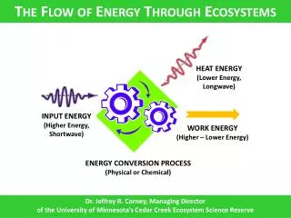
Computational Evaluation of the Cavitating Flow through Automotive Torque Converters Acknowledgement: This work is supported by the General Motors Corporation 15 August 2012 J.W. Lindau F.J. Zajaczkowski M.F. Shanks R.F. Kunz. CONTENTS. Introduction Computational Methods Results

E N D
Computational Evaluation of the Cavitating Flow through Automotive Torque Converters Acknowledgement: This work is supported by the General Motors Corporation 15 August 2012 J.W. Lindau F.J. Zajaczkowski M.F. Shanks R.F. Kunz
CONTENTS • Introduction • Computational Methods • Results • Summary
Introduction: Automotive Torque Converter • CAVITATION IN A TORQUE CONVERTER: • Working fluid is ATF, heat, extreme pressures • Torque converters have historically not suffered negative effects from cavitation • However, the trend is to smaller, lighter, etc • Minimum pressure/stator region may cavitate at high torque, low turbine speed • Concerns are performance, vibration, noise Torque Converter from Wikipedia
Methodology • First principals model of… • Mixture of gases and liquids • Gas-liquid interfaces • Large scale gas cavities • Incompressible to compressible: disparate sound speeds • Shocks • Significant inherent unsteadiness (even in steady, planing configuration) • Energetic propulsion • Chemistry and phase change • Liquid/vapor mass transfer (stiff) • Chemical reactions (stiff) • Control Surfaces--6DOF: fully coupled to flow • Preconditioning (addresses stiff physical eigensystem) • Turbulence modeled and (where feasible, required) simulated • Numerical model: fully-conservative, unsteady, implicit, multiphase, preconditioned finite volume form • Unsteady simulations with many millions of degrees of freedom are feasible/required
DIFFERENTIAL MODEL • Computational tool— • n-liquid+n-gas • preconditioned • all-Mach number • compressible • total energy conservation • any 2-variable eos/species • body forces/propulsors • mass-transfer=phase change and chemistry • shock-capturing • level-set—free-surface or cavity interface • multibody-control surfaces-6DOF • overset • 2-eq RANS/DES/transition Numerical solution of mixture: mass, momentum, energy, additional phases, species, and turbulence models on moving or static, overset computational meshes.
VALIDATION HIGHLIGHTS Cavitator Lift and Drag
VALIDATION HIGHLIGHTS Lift and drag values and comparison of experimental and computational geometries and computed cavities (with gas streamlines) from experiments of Waid and Kermeen (1957).
VALIDATION HIGHLIGHTS Cavity Size vs. Ventilation Rate
VALIDATION HIGHLIGHTS Mesh showing flowpath, rotor, and stator in NSWC-CD Tunnel Normalized Power Normalized Head Rise Normalized inlet total pressure
Torque Converters: Computational Mesh turbine pump turbine pump stator stator COMPUTATIONAL GEOMETRY REPEATED OVER FULL 360deg Thin Torus: Converter Approximating Current Designs Trends BOTH A MIXING PLANE AND A BODY FORCE BASED COUPLING APPROACH ARE APPLIED Round Torus: Research Converter
MPa b) a) Round Torus CFD Results Cavitating CFD current effort 0.8 0.0 Single Phase CFD current effort CFD and test results on research converter. K-factor (RPM/[torque]1/2) and torque ratio.
Thin Torus CFD Mesh Pump Through-flow Stator Turbine Grids for body force based method. Computational meshes, thin-torus torque converter (coarse). Solid surfaces are illustrated with black mesh. Periodic boundaries are illustrated with green mesh.
Thin Torus CFD Results CFD results (red) diamond: cavitating square: 1-phase Dyno-250 N-m K-factor/100 Dyno-135 N-m Torque Ratio Speed Ratio • Computation and testing of Thin Torus TC. • Single-phase and cavitating. Plot of K-factor/100 and torque ratio versus speed ratio. • Dynomometer: black marks with black lines. • CFD: red diamonds and dashed==single-phase, and • CFD: red squares and dashed ==cavitating
MPa MPa Thin Torus CFD Results 0.5 1.1 0.0 0.0 suction side pump and stator pressure-side pump and stator Single-phase solution, pump at 3000RPM, turbine stationary, thin-torus torque converter. Cavitating CFD solution, thin-torus unit. Elements repeated periodically for visual effect. Surfaces made translucent to better visualize stator and cavity. All surfaces colored by pressure. Isosurface of vapor volume fraction at 0.5. Pump at 3000RPM, stall condition
SUMMARY • CFD methodology validated for ventilated and natural cavitation, supercavitation, and turbomachinery • Torque converters modeled using single blade passage, multi-blade row (steady, periodic assumption) CFD • Mixing plane and body force coupling • Both approaches are problematic • Cavitation effects on pump torque captured • For high torque/large cavities and impact on noise/vibration, a full 360deg unsteady analysis may be needed
Preconditioner Derivation simplified working in terms of mass fraction
Preconditioner • We choose: c’=min[ max( Vcut-off , |V|ijk ), cijk ] (c’=cijkyields the unconditioned result) • Introduces artificial sound speeds yielding good convergence/accuracy regardless of Mach number/density ratio