Download
1 / 21
210 likes | 410 Vues
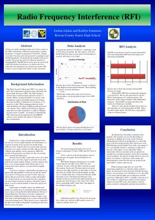
Studies of Radio Frequency Interference Effects at C-band. IGS Quarterly Review Joel T. Johnson. 6.8 GHz H Max over 6 months. 10.7 GHz |U| Max over 6 months. T B [K]:. T [K]:. C- and X-band RFI in WindSat Data. Both C- and X-bands have no significant protected spectrum for radiometry

E N D
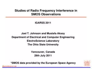
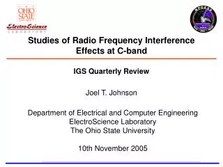
Studies of Radio Frequency Interference Effects at C-band IGS Quarterly Review Joel T. Johnson
6.8 GHz H Max over 6 months 10.7 GHz |U| Max over 6 months TB [K]: T [K]: C- and X-band RFI in WindSat Data • Both C- and X-bands have no significant protected spectrum for radiometry • Data from both AMSR-E and WindSat radiometers show RFI problems • Increasing transmissions in these bands compromise EDR retrievals, esp. soil moisture and sea surface temperature • IPO/CMIS contractor have proposed a multi-channel C-band receiver for CMIS, no modifications for X-band
C-band Channel Frequencies IPO simulations using databases of registered emitters used to develop current CMIS channel plan Multiple channels used in a cross-freq RFI detection algorithm; discard corrupted channels Multi-channel airborne data available from PSR/C since 1999 High frequency/time resolution data obtained from CISR since 2004 under this project
Purpose • GOAL 1: Acquire airborne high resolution data to improve knowledge of C-band RFI environment and to validate and enhance CMIS RFI forecasts • GOAL 2: Demonstrate improvements in RFI mitigation that can be obtained through advanced receiver technologies • Project is a collaboration between OSU, NOAA/ETL, and Virginia Tech: • NOAA/ETL PSR/C provides antenna/front end in airborne campaigns • OSU provides RFI observing and mitigating receiver backend • Virginia Tech assists in data analysis and interpretation • NOAA/ETL and OSU hardware leveraged off of other system development projects (a NASA IIP for OSU); only minimal hardware support from IPO • OSU backend is a FPGA based-digital receiver; can configure into several observational modes
Outline • Administrative Information • Advanced Radiometer Receiver • Summary of Accomplishments • Current Efforts and Future Plans
Administrative Information • Project schedule and budget information: • 8/03- 12/03: Initial system development (30K) • 1/04- 12/04: Deployed in SMEX04 and AASI04 exp (125K) • 1/05- 12/05: Data analysis, deployed in WB-57F (125K) • Who is involved: • Johnson + students/staff (Ohio State) • Steve Ellingson + students/staff (Virginia Tech) • Al Gasiewski + staff (NOAA/ETL) (under other IPO support) • Funding Status: • Funded through end of project (12/31/05) • Developing proposal for continued RFI studies
Pulsed interferer (~msec) Time Radiometer integration period (~msec) Advanced Radiometer Receiver • Properties of traditional radiometer: • very “slow” instrument • power integrated for msec before being digitized • a single, large bandwidth channel • susceptible to narrow band interference • Our design uses a digital receiver for rapid sampling • can mitigate temporally localized RFI in real time • Our design samples 100 MHz, and performs a 1024 point FFT • can mitigate spectrally localized RFI, tuned throughout C-band • Processor operates in real time to reduce final data rate • implemented in hardware (FPGA’s) • C-Band Interference Suppressing Radiometer (CISR)
Digital Receiver Backend • Digital receiver samples 100 MHz and includes pulse blanking and 1024 point FFT processor • Samples IF from PSR downconverter; 22 100 MHz channels from 5.5-7.7 GHz • Can compare data against simultaneous PSR analog sub-channels; assess PSR 4-channel RFI algorithm 200 MSPS 10 bit ADC’s Implemented in Altera FPGA’s Real-time “pulse blanking” algorithm 1K FFT = high spectral resolution RFI removal Spectral processing/ integration 1K FFT Digital filtering/ pulse blanking • Example data: high spectral resolution for CW and wideband RFI mitigation • Numerous sources observed; compare observations to IPO forecasts • Most sources observed are continuous, pulsed sources < 5.8 GHz only
Summary of Accomplishments • Datasets obtained from three deployments: • SMEX04 (August, Tuscon, AZ and Northern Mexico, Navy P-3) • Small dataset recorded, interface and system issues resolved • AASI04 (October, test flight near Wallops Island, VA, Navy P-3) • Approximately 2 hours of data recorded, numerous RFI sources • WB-57F test flight (August 05, high altitude flight over Texas cities) • Approximately 2 hours of data recorded, numerous RFI sources • Detailed analysis of AASI04 data provides info on RFI source properties + assessment of 4 sub-band mitigation algorithm • Examples obtained to illustrate advantages of digital receiver • RFI analysis of WindSat data performed in support of these efforts • Matchups of AASI04/WB-57 RFI with source database in progress
AASI04 Test Flight • The largest CISR dataset is from a test flight on October 8th, 2004 in preparation for the AASI04 campaign • Note PSR includes 4 analog C-band channels for RFI mitigation (5.8-6.2, 6.3-6.7, 6.75-7.1, 7.15-7.5 GHz) • Comparison of PSR/ CISR data enables test of digital vs. analog methods • Use NOAA/ETL algorithm for RFI removal in 4 sub-band data Circles in Figure mark WFF and NDBC Buoy
PSR Images: AASI04 Test Flight over Buoy Time Time
Corresponding CISR Data (to 6.1 GHz) Provides precise knowledge of RFI center frequency Allows possibility of frequency domain blanking to remove RFI Calibrations show frequency domain blanking effective against narrowband RFI
CISR Advantages over PSR Calibrated CISR data for the point marked with green line shows narrowband RFI in PSR channel 4; calibration shows contribution ~4-5K to PSR PSR 4 x400 MHz channels show strong RFI; 4 channel algorithm chooses channel 4 (least corrupted) as correct
Use of Asynchronous Pulse Blanking (APB) at C-band • APB on/off data was recorded by CISR throughout C-band • Results >5.8 GHz show no influence of blanker • Results < 5.8 GHz show strong influence of blanker • As expected from freq. allocations in US Maximum raw data observed 5.7-5.8 GHz
WB-57F Deployment CISR onboard WB-57 • Test flight over Texas cities, 8/25/05 • PSR/C, CISR, and CADD sensors • Datasets can be intercompared to assess performance • CISR provides highest spectral resolution • High altitude (18.9 km) environment of unpressurized WB-57 payload bay thermally challenging NASA WB-57F Flight Plan
Example Matchup Studies • IPO has made JSC unclassified source database available, contains data from 4.9-5.9 GHz, 6.2-7 GHz • Database includes power, antenna, and sometime pol info Source Locations near Flight Path Histogram of Source Center Frequencies
PSR Interference Level Statistics 21600 PSR pixels in more rural Texas: 18:08-18:23 UTC 21600 PSR pixels near DFW: 17:54-18:08 UTC
Current Efforts and Future Plans • Will continue analysis of datasets until project end at 12/31/05 • Database matchups will test methods for forecasting received brightness from database information • We believe that sufficient datasets exist at this point to perform a comprehensive review of C-band RFI for CMIS • Utilize satellite, aircraft, and database information in a combined study • Produce an improved RFI forecasting tool for CMIS • Produce an improved 4 channel mitigation algorithm • Provide recommendations to IPO regarding CMIS freqs • Assess new technologies for future CMIS instruments • X-band RFI also needs examination: PSR has 4 sub-bands, AMSR/E and WindSat show problems outside US
Summary • Project has provided a set of high time and frequency resolution airborne data to improve knowledge of C-band RFI environment • Project has provided qualitative evidence of potential failure modes for four channel RFI mitigation algorithms • Project has demonstrated that advanced receiver technologies can improve RFI mitigation • Analysis of data continuing, including assessment of forecasts based on source database information • Currently proposing continued studies to the IPO in collaboration with NOAA/ETL, Virginia Tech, University of Michigan, and NASA GSFC
Project Publications • J. T. Johnson, A. J. Gasiewski, et al, “Airborne radio frequency interference studies at C-band using a digital receiver,'' submitted to IEEE TGRS, 2005. • S. W. Ellingson and J. T. Johnson, “A polarimetric survey of radio frequency interference in C- and X-bands in the continental United States using WindSat radiometry,'' to appear, IEEE TGRS, WindSat special issue. • J. T. Johnson, A. J. Gasiewski, et al, “Airborne radio frequency interference studies at C-band using a digital receiver,'' IGARSS’04. • S. W. Ellingson and J. T. Johnson, “Measurements of L- and C-Band RFI from Earth observing remote sensing instruments,'‘ Workshop in Mitigation of Radio Frequency Interference in Radio Astronomy, 2004. • J. T. Johnson and S. W. Ellingson, “A polarimetric survey of RFI in C- and X-bands in the continental United States using WindSAT radiometry,” APS/URSI 2005.