Download
1 / 21
220 likes | 376 Vues
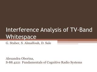
Interference Analysis of TV-Band Whitespace. G. Stuber, S. Almalfouh, D. Sale Alexandra Oborina, S-88.4221 Fundamentals of Cognitive Radio Systems. Outline. Motivation IEEE 802.22 WRAN WRAN Cell and Television service contours Tolerable levels of Interference Simulation Results

E N D
Interference Analysis of TV-Band Whitespace G. Stuber, S. Almalfouh, D. Sale Alexandra Oborina, S-88.4221 Fundamentals of Cognitive Radio Systems
Outline • Motivation • IEEE 802.22 WRAN • WRAN Cell and Television service contours • Tolerable levels of Interference • Simulation Results • Conclusions
Motivation • There is a spectrum shortage due to licensing process that limits the ability of spectrum users to gain access to available spectrum. • The broadcast television spectrum (TV bands) is particularly attractive for the deployment of CR systems, due to its relatively low propagation path loss when compared to other higher frequency bands. • In Oct. 2006, FCC reported that fixed low-power devices could operate in unused TV channels without causing harmful interference to primary services. • In Nov. 2006, IEEE 802.22 WRAN is established to provide fixed wireless broadband services using vacant TV channels without causing harmful interference to incumbent TV broadcast signals and other TV-band devices such as wireless microphones. • This study aims to determine the tolerable levels of interference caused by WRAN installed in a home to nearby DTV receivers.
IEEE 802.22 WRAN Overview • IEEE 802.22 is a standard for Wireless Regional Area Network using white spaces in the TV frequency spectrum on a non-interfering basis. • In the USA the TV bands use UHF/VHF radio spectrum: 54-72, 76-88, 174-216 and 470-806 MHz. • Aim of IEEE 802.22 WRAN is to use CR to bring broadband access to hard-to-reach, low population density areas (rural environments). • IEEE 802.22 WRAN air interface is based on IEEE 802.16e with signal channel operation over 6 MHz. TDD OFDMA with 2048 subcarriers, variable CP, AMC (from QPSK1/2 to 64QAM5/6 ). WRAN is able to utilize up to three adj. TV channels at a time through “Channel bonding”.
IEEE 802.22 WRAN Overview • System topology: The system is point (BS) to multipoint (CPE). The BS additionally to traditional functionality manages ''the cognitive radio aspects''. It uses CPE to perform the distributed measurement of a signal level of possible TV signals on the various channels at individual locations. From these measurements BS decides whether any actions are to be taken. • Coverage area: Typical cell size is from 33 km (EIRP is 4W) up to 100 km. • System capacity: The system is defined to achieve a level of performance similar to DSL services. User capacity in DL is 1.5Mbps, in UL is 384 Kbps, overall DL system capacity 18 Mbps with average spectral efficiency 3 bits/s/Hz.
Television service contours • NTSC television services in North America are deployed according to Grade A and Grade B protected noise-limited contours. • These contours are calculated according to FCC specific procedure taking into account receiver sensitivity, antenna gain, and transmission-line loss of the receiving system. • The contour is specified by the electric field strength (in units of decibels) above 1 mV/m at a height of 10 m above ground and subjective picture quality. • For DTV services, the Grade B service contour is the area with the median field strength >= required to produce a picture that a median observer classifies as ''acceptable for at least 90% of the time in the best 50% of the receiving locations located on the contour. • For UHF band the defining field strengths for DTV service is 41 dBu and desired signal input power level is -84.2 dBm.
WRAN Cell • WRAN cell is composed of a base station (BS) and a number of customer premise equipment (CPE) terminals installed in customer homes. • CPE antenna should be mounted 10m above the ground and should be at least separated by 10 m from the closest DTV antenna. • If there is a DTV station transmitting in channel N in the UHF band, then no BS or CPE located inside the Grade B contour should operate on channel N or N +-1. • BS located outside the Grade B contour and operating on channel N or N +-1 must be separated from the DTV BS by a minimum distance called the keepout distance. • This distance depends on the maximum allowable effective isotropic radiated power (EIRP) of the WRAN BS and the channel separation between the WRAN and the DTV channel. • WRAN BS and CPE operation inside the Grade B contour is permitted for channels N + i, i > 1, subject to limiting their EIRP below certain levels to avoid interference to nearby DTV receivers.
Why tolerable levels of interference are needed • Reason: In many countries not all available TV channels are used as it is necessary to allow guard channels between active high power transmitters to prevent mutual interference. • Goal: determine the max CPE EIRP values and out-of-band emission that will not cause harmful interference to nearby DTV receiver.
Experimental arrangements • The DTV signal is placed in channel N at 539 MHz, 6MHz BW, at input signal levels of -53 dBm (moderate desired), -68 dBm (weak desired), -76 dBm (Grade B +7) and -83.5 dBm (near Grade B). • WRAN CPE antenna is mounted at 10 m above the ground and is separated by at 10 m from any nearby DTV receive antenna. • Single WRAN interferer is placed in channel N+1 ( adjacent channel) and in channels N+2:N+15 (taboo channels). • WRAN with 99% uplink loading represents the worst case interference to a DTV receiver. It guarantees acceptable DTV performance under all WRAN traffic conditions. • 2 different DTV receiver models were tested (DTV-A and DTV-B).
Noise limited Thresholds • a high quality image total loss of image • DTV-A -83.5 dBm -83.6 dBm • DTV-B -84.3 dBm -84.9 dBm • DTV receivers are designed to have a noise limited thresholds very close to Grade B input signal level (-84.2 dBm) • Typical DTV receiver will not tolerate any additional adjacent or taboo channel interference if it operates at near Grade B input signal level.
Taboo Rejection Thresholds • Power of WRAN signal is increased in steps by 0.1 dB untill a high quality DTV image is present. • The threshold values are reported as desired-to-undesired ratios • D/U = P(DTV signal in N channel)– P(WRAN signalin channel N+i) • So, D/U is the smallest value such that high quality DTV image is presented. • The desired DTV input signal levels : A) -53 dBm (moderate desired) B) -68 dBm (weak desired) C) -76 dBm (Grade B +7) D) -83.5 dBm (near Grade B)
Taboo Rejection Threshold Results • Both tested receivers exhibited quite similar WRAN into DTV rejection thresholds. • Increased image interference can be present on channels N + 7, N + 14, and N + 15. • The adjacent and taboo channel rejection thresholds on the second and third adjacent channels tend to be degraded for WRAN into DTV interference.
Taboo Rejection Threshold Results • The DTV receivers appear more sensitive to WRAN adjacent channel interference than to DTV adjacent channel interference at the weak and Grade B + 7 input signal levels, i.e., the D/U values are larger.
Required SIR and Out-of-band Emissions Levels • Goal: determine how the DTV receiver is being limited by the WRAN signal power in the N+i channels • SIR is measured by DTV-A receiver in N channel, where C is the desired DTV input signal power, and I is WRAN interference power presented in N+i channel at the rejection threshold.
Co-channel Rejection Thresholds (noise) • At very low desired signal input levels, such as the Grade B input level, signal reception is limited by the internal DTV receiver noise power N2. • It is desirable to know N2 in order to make more accurate estimates of performance degradation due to co-channel or other in-band interference from signals that are present in adjacent and taboo channels. • In practice, it is not possible to measure the internal noise source N2. However, it is possible to infer N2 from a series of measurements external to the receiver. • Once N2 is determined for a specific DTV receiver, it is possible to determine how much WRAN co-channel interference can be tolerated by the DTV receiver.
Co-channel Rejection Thresholds (noise) • C is DTV signal input level, N1 is external noise and N2 is internal noise. • For high C and N1 level • C/(N1+N2) ~ C/N1 = SNRreqd • SNRreqd is a threshold value such that the DTV receiver produces a stable picture, yet any reduction in C/N1 causes the picture to degrade. • When SNRreqd is determined, N2 can be obtained by varying C/N1 while keeping C/(N1 + N2) at the threshold operating point.
Co-channel Rejection Thresholds (noise) • The value of SNRreqd is determined by adjusting C = -40 dBm and increasing N1 to the threshold level where a 0.1 dB further increase results in noticeable DTV image degradation. • SNRreqd = 13.2 dB for DTV-A and SNRreqd = 12.7 dB for DTV-B • For very low desired signal input power level, where the internal noise source N2 dominates the total SNR, N2 is considered constant and a substantial increase in C/N1 is required to obtain an acceptable DTV image.
Co-channel Rejection Thresholds (interference) • The maximum tolerable WRAN interfering power is determined by • For co-channel WRAN signals (and no noise) SIRreqd must exceed 15.6 dB, even for strong DTV signals, for both receivers. • Conclusion: no additional degradation beyond the internal receiver noise can be tolerated.
CPE transmit filter attenuation and max CPE power • The maximum allowable CPE transmit power can be determined from a link budget analysis under the assumption of typical DTV and WRAN CPE deployments with the help of taboo channel rejection thresholds. • Out-of-band emission limit can be calculated as function of contour field strength, SIRreqd and some other parameters. • The CPE transmit filter attenuation that is required to meet the out-of-band emission limit can be determined as max WRAN field strength – out-of-band emission limit – DTV receive antenna discrimination
Conclusions • The results show that it is not possible to permit WRAN operation while protecting DTV receivers that are operating at the Grade B input signal level. • However, WRAN operation is possible at the Grade B + 7 contour signal level, although the maximum allowable CPE transmit EIRP is less than the maximum permitted 4 W and is on the order of 0.5 W for the DTV tested receivers. • The results show that there is a significant variability in D/U performance of different TV sets. To guarantee that WRAN operation will not impair DTV reception, many DTV makes and models should be tested to find the one that exhibits the worst D/U performance.