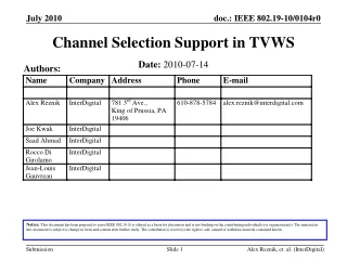
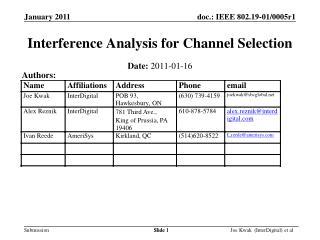
Interference Analysis for Channel Selection
Interference Analysis for Channel Selection. Authors:. Date: 2011-01-16. Slide 1. Outline. Introduction Pairwise link analysis approach applied to population of TVBDs

Interference Analysis for Channel Selection
E N D
Presentation Transcript
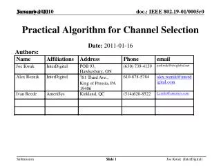
Interference Analysis for Channel Selection Authors: Date: 2011-01-16 Slide 1 Joe Kwak (InterDigital) et al
Outline • Introduction • Pairwise link analysis approach applied to population of TVBDs • Interference from new transmitter at specific location is analyzed for each receiver in population at their locations. PTx-max is calculated to produce interference level at receiver which is below Rxsensitivity level for that receiver. • Interference from each transmitter in population is analyzed for location of new receiver. Interference vectors are summed to calculate Pint-tot • Result for each channel is PTx-max (maximum TX power permitted on channel) and Pintf (total interference power received on channel). • Select subset of channels which have useable PTx-max • Select from subset channel with lowest Pint-tot • The channel so selected is the best one to use. • Observations • Conclusions Joe Kwak (InterDigital) et al
RT-A1 RT-A3 RT-A2 Map of Channel Users on Chan A I-94 I-65 Joe Kwak (InterDigital) et al
RT-B1 RT-B2 Map of Channel Users on Chan B I-94 I-65 Joe Kwak (InterDigital) et al
RT-C1 RT-C2 Map of Channel Users on Chan C I-94 I-94 I-65 I-65 Joe Kwak (InterDigital) et al
RT-A1 RT-A3 RT-A2 RT-B1 RT-B2 RT-C1 RT-C2 All TVWS users with New User RT-new I-94 I-94 I-65 I-65 Joe Kwak (InterDigital) et al
Do pairwise link analysis for chan A • T-new to R-A1 Link: • Compute PL (path loss) considering • LOS (path elevation from topology dbase) • Distance and propagation losses • Tx antenna (at T-new) gain • Rx antenna (at R-A1) gain • Possible other losses: foliage, buildings, indoor/outdoor, etc • Compute Intf-max (max interference at R-A1) as 6dB below RXsensitivity of R-A1 • PTx-max(a1) = Intf-max + PL == is the Max Tx power of T-new • Repeat above for R-A2 and R-A3. • Result is list of PTx-max: -10dBm, 3dBm, 13dBm • The lowest power in list is the maximum transmit power allowedat T-new. • PTx-max(total) = -10dBm Joe Kwak (InterDigital) et al
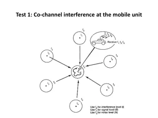
Do pairwise link analysis for chan A • T-A1 to R-new Link: • Compute PL (path loss) considering • LOS (path elevation from topology dbase) • Distance and propagation losses • Tx antenna (at T-A1) gain • Possible other losses: foliage, buildings, indoor/outdoor, etc • Compute Pintf at R-newas vectorwith azimuth from R-new to T-A1 (from receiver's viewpoint) and magnitutde equal to PTx-A1 - PL = Pintf(a1) • Repeat above for T-A2 and T-A3. • Result is interference diagram at R-new • Superpose receive antenna gain and compute sum of interference powerfrom all sources. • Result is Pintf(total) = -60dBm -83dBm from T-A3 -77dBm from T-A2 -60dbm from T-A1 Joe Kwak (InterDigital) et al
Channel Summary • The prior two slides show the result of the analyses for channel A: • PTx-max(total) = -10dBm • Pintf(total) = -60dBm • Similar analysis is repeated for all other TVWS channels in use, In this example for channel B: • PTx-max(total) = +13dBm • Pintf(total) = -80dBM • Similar analysis is repeated for all other TVWS channels in use, In this example for channel C: • PTx-max(total) = +13dBm • Pintf(total) = -85dBM • When all channels results are tabulated, simple two step selection algorithm can be used. Joe Kwak (InterDigital) et al
Algo Step One: Required Ptx • The new RT, RT-new provides an operating power request when registering with the CSS. This PTx-req value is used to eliminate channels with PTx-max lower than the requested value. • PTx-max = [-10dBm, +13dBm,+13dBm] for chans A-C • Because PTx-req is +10dBm, channel A is eliminated. • Channels B and C are still candidates. Joe Kwak (InterDigital) et al
Algo Step Two: Select lowest Pintf • The Pintf values for all channels are • Pintf = [null, -80dBm, -85dBm] for channels A-C • Channel A is marked null since it was eliminated in step one. • Selecting the lowest Pintf from the array of channels is easy and results in the selection of channel C as the best choice for channel assignment. • This example demonstrates a complex pairwise link analysis approach to characterize the channels in use using two parameters: PTx-max and Pintf. • The channels selection algorithm is a two step simple process. Joe Kwak (InterDigital) et al
Applying Link Analysis to all TVBDs • Permits the interference on channel to be easily summarized at any given location: • Channel characterized by list of vectors for Ptx-max: • -10dBm-max @ 20deg (outbound emanation limits) • -40dBm-max @ 180deg • 30 dBm-max @ 270deg • Channel characterized by list of vectors for Pintf: • -70dBm @ 20 deg (inbound interference) • -40dBm @ 180deg • -95dBm @ 270deg • Channel interference condition • {Ptx-maxi, i=1-n} set of tx limit vectors, minimum applies • SUM(Pintfi, i=1-n) sum of interference vectors Joe Kwak (InterDigital) et al
Interference Analysis & Antenna Gains • Allows vector sets to be summarized into single scalars • Multiply (dB add) Ptx-max vectors by antenna gain in each direction. • The lowest resulting single scalar value is the max TX power for that TVBD on that channel at that location. • Multiply (dB add) Pintf vectors by antenna gain in each direction. • The sum of the scalar powers is equal to the total interference for that TVBD on that channel at that location. Joe Kwak (InterDigital) et al
Coexistence Environment in Channel Map • For any TVBD at any location, the coexistence environment can be so summarized for all "FCC available channels". • TVBDa at LOCx (when FCC lists 14, 22 & 28 as available): • Chan 14: -10dBm Ptx-max, -60dBm interference • Chan22: -20dBm Ptx-max, -40dBm interference • Chan28: +20dBm Ptx-max, -90dBm interference • This may be used as "Channel Map" for that TVBD at that location. • Note default values for vacant channel: • Vacant: +36dBm (or +16dBm for pers/port) Ptx-max, -110dBm interference (TBR?) Joe Kwak (InterDigital) et al
Observations on this Approach • The proposed approach described here is tractable, scales linearly with the number of RTs within interference range, and can be described in simple normative terms suitable for a standard. • The drawback to any simplified approach is that it may not consider many other secondary effects, which, when taken together, may not be negligible, i.e., adjacent channel effects, non uniform channel bandwidths in use, etc. • This approach defines a "Channel Map" which is an analytic view of the coexistence environment at a TVBD's location at a given time. This Channel Map is a key value added service that the CDIS/CM may provide to subscribing TVBDs. • The Channel Map does not rely on definitions for Neighbor and Channel State and does not need classification of neighbors or channels. Joe Kwak (InterDigital) et al
Further Observations • This practical approach may be implemented using only an internet based elevation profile tool. A very simple one is available at http://www.heywhatsthat.com/profiler-0904.html • This tool (or more complex ones) may be used between any two geographic points with known antenna heights to compute a line of site path elevation profile. • Better geographic data from published 3-D databases may also be used for elevation profiles and LOS evaluation. GERDCS uses such a 3-D database. • The elevation profile is used to determine if LOS exists. If LOS between link nodes does not exist, the node is removed from further analysis. Diffraction in Fresnel zone complicates this somewhat. LOS exists here Joe Kwak (InterDigital) et al
Open Issues • Any approach will need to address location uncertainty: what to do when location of Mode I device is only known to be within coverage area of AP or controlling Mode II device?? • For this case the pt-pt approach proposed here can work, but only when multiple LOS paths are used to determine the closest LOS location within the coverage area. The location so determined may be used as the "worst case" location for coexistence analysis. • Diagram on next chart explains this approach. • Further details to include effects of Tx output power in adjacent channels and use of variable bandwidth channels may be developed in future meetings. Joe Kwak (InterDigital) et al
Representative links to use when location is uncertain. : Nearst location with LOS Location to Use When Location is Uncertain Uncertainty area for TVBDa Ridge slightly above TVBD TVBDc LOCc-a LOCb-a TVBDb Ridge slightly above TVBD Joe Kwak (InterDigital) et al
Coexistence is all about Interference Levels • The 802.19.1 specification requires a channel selection algorithm that realistically considers all relevant propagation and interference aspects of the TVWS radio environment: • Locations for all TVBDs • TVBD characteristics: • Channel in use • Ptx in use • RXsensitivity of receiver in use • TX spectrum on adjacent channels • Rx receiver intermods • Variable channel BWs • Antenna type (indoor/outdoor), height and gain characteristics • Path loss and link analyses computations considering • Interference path distance • Interference path LOS • Interference path characteristics: urban, country, foliage, etc • This approach and the GERDCS approach and are identical and is the only proposal that realistically address all these considerations. CONCLUSIONS: • This approach provides a TVBD a value added interference channel map. • This approach uses a tractable, straightforward method for channel selection which scales linearly with number of TVBDs. Joe Kwak (InterDigital) et al
Discussion Joe Kwak (InterDigital) et al