Download
1 / 11
110 likes | 295 Vues
CH.1 Introduction 1-1 Introduction ˙Power electronic circuits convert electric power from one form to another using electronic device (switch). ˙Relatively small power loss in the device. ˙Real devices absorb some power when in the on state and when

E N D
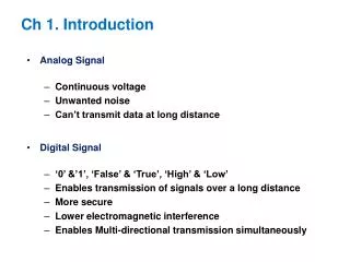
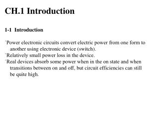
CH.1 Introduction 1-1 Introduction ˙Power electronic circuits convert electric power from one form to another using electronic device (switch). ˙Relatively small power loss in the device. ˙Real devices absorb some power when in the on state and when transitions between on and off, but circuit efficiencies can still be quite high.
1-2 Converter classification ˙AC-DC converter ------- Rectifier ˙DC-AC converter ------- Inverter ˙DC-DC converter ------- Chopper ˙AC-AC converter ------- (AC Voltage Controller)
1-3 Electronic switches Diode : Fig.1-1
Rectifier Diode : reverse recovery time trr < 1μs become important in high-frequency applications. Scottky diodes : metal-to-silicon barrier rather than a p-n junction. forward voltage drop ≒0.3V.; turn on and off faster than p-n junction diodes. Thyristors: Fig.1-2 →Three-terminal devices;switching fre. =10~20kHz;in high- power applications.
Transistors : Fig.1-3~1-5 are operated as switches ( in the fully on or fully off state )in power electronics circuits, not operated as an amplifier circuit. ( in the active or linear region ). include bipolar junction transistors (BJTs), MOSFET, insulated-gate bipolar junction transistors.(IGBTs).
BJTs : Rating up to 1200V, 400A; operating up to approximately 10kHz. Power BJTs generally are available in higher voltage and current rating than MOSFETs. A current-controlled device.
MOSFET : A voltage-controlled device; are of the enhancement type rather than the depletion type. Drive circuit to turn a MOSFET on and off is usually simpler than that for a BJT. Rating are up to 1000Vand 50A. Switching speeds are faster than BJT and up to/beyond the 100kHz range.
IGBT : is an integrated connection of a MOSFET and a BJT. The drive circuit is like that of the MOSFET, while the on-state characteristics are like that of the BJT. Switching speeds up to about 20kHz and have replaced BJT in many applications.
1-4 Switch selection • depends not only on the required voltage and current levels but also on its switching characteristics. • GTOs provide the control of both turn-on and turn-off, SCRs of turn-on but not turn-off, and diodes of neither. • The BJT is a minority-carrier device, whereas the MOSFET is a majority-carrier device which does not have minority-carrier storage delays, giving the MOSFET an advantage in switching speeds. • BJT switching times may be a magnitude longer than for the MOSFET. Therefore the MOSFET generally has lower switching losses.
GTO : Can be turned off with a negative gate current,but its magnitude must be very large compared to the turn-on current. Triac : is capable of conducting current in either direction; is equivalent to two antiparallel SCRS. MCT: is equivalent to the GTO but without the high turn-off gate current requirement;has an SCR and two MOSETs. One MOSFET turns the SCR on,and one MOSFET turn the SCR off.