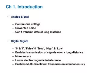
Ch 1. Introduction
Ch 1. Introduction. Analog Signal Continuous voltage Unwanted noise Can’t transmit data at long distanc e. Digital Signal ‘0’ &’1’, ‘False’ & ‘True’, ‘High’ & ‘Low’ Enables transmission of signals over a long distance More secure Lower electromagnetic interference

Ch 1. Introduction
E N D
Presentation Transcript
Ch1. Introduction • Analog Signal • Continuous voltage • Unwanted noise • Can’t transmit data at long distance • Digital Signal • ‘0’ &’1’, ‘False’ & ‘True’, ‘High’ & ‘Low’ • Enables transmission of signals over a long distance • More secure • Lower electromagnetic interference • Enables Multi-directional transmission simultaneously
1.3 Digital Devices • Gate • The most basic digital devices • Got there name from their function (AND, OR…) • Gate has one or more inputs and produces output that is function of current input values
2 input AND gate 2 input OR gate
1.4 Electronic Aspects of Digital Design Logic Function • Noise Margin • The voltage difference between the guaranteed output level and the required input voltage of a logic gate • In a real circuit, a gate’s output can be corrupted by this much noise Electronic Function
1.5 Software Aspects of Digital Design • Software Tools • CAD • Schematic Diagram • HDLs • Text editors • Compilers • Synthesizers • Simulators • Test Benches • Timing Analyzers Ex) Modelsim, Xilinx, Synplify, XST
HDL • Hardware Description Language • 1980년대 초부터 미 국방성에서 사용시작 • 1981년 VHDL (VHSIC Hardware Description Language) 제안, • 이후 IEEE 표준으로 채택 • HDL 이전 • - Layout editor나Schematic editor를 사용 • 작은 블록을 설계하고 큰 블록을 설계하는 Bottom-up 방식 • 회로의 규모가 커지고 복잡도가 증가함에 따라 한계 발생 • HDL 이후 • 알고리즘이나 기능 레벨에서 설계가 가능 • Top-down 방식 • 복잡한 회로의 설계 가능
1.6 Integrated Circuits • IC (Integrated Circuit) • Collection of one or more gates fabricated on a single silicon chip • SSI (Small Scale IC) →MSI (Medium Scale IC) →LSI (Large Scale IC) → VLSI (Very Large Scale IC)→SoC (System on Chip) → NoC (Network on Chip) • pad, die
1.7 Programmable Logic Devices • PLA (Programmable logic array): Only two level structure (AND, OR) • PAL (Programmable array logic), PLD(Programmable logic device) • →CPLD(Complex PLD)→FPGA(Field-programmable gate array)
1.10 Digital-Design Levels input output
Turn on when ‘0’ output input Turn on when ‘1’
2-input 4-bit MUX Input : A and B (0~4bits) Output : Z (0~4bits)