Linac4 Status
Linac4 Status. M. Vretenar for the Linac4 team. B I Review 18 .10.2011. Linac4 motivations. Present LHC injection chain: Linac2 (50 MeV) ↓ PS Booster (1.4 GeV) ↓ PS (25 GeV) ↓ SPS (450 GeV) ↓ LHC.

Linac4 Status
E N D
Presentation Transcript
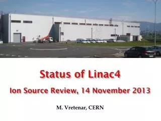
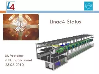
Linac4 Status M. Vretenar for the Linac4 team BI Review 18.10.2011
Linac4 motivations Present LHC injection chain: Linac2 (50 MeV) ↓ PS Booster (1.4 GeV) ↓ PS (25 GeV) ↓ SPS (450 GeV) ↓ LHC New 160 MeV H- linear accelerator to replace Linac2 as injector to the PS Booster. Project approved in June 2007, started on January 1st, 2008. MOTIVATIONS: Make possible an upgrade of the LHC luminosity beyond nominal, by reducing space charge at PSB injection (factor 2 in bg2 and brightness going from 50 to 160 MeV). More modern and sustainable than Linac2 (worries for long-term operation of Linac2 ). Flexible operation and reduced loss with new technologies (chopping, H- injection). Higher intensity for non-LHC users. Prepare for a possible high-intensity upgrade (neutrino facility).
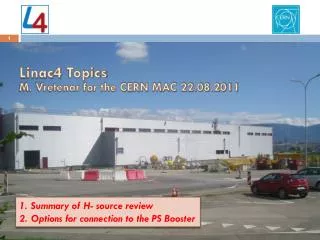
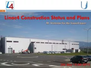
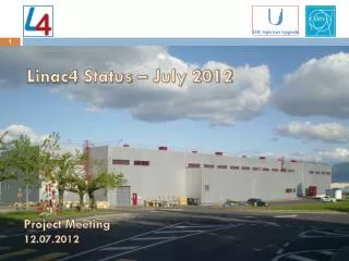
Linac4 on the CERN site • About 100m in length, built on one of the last “free” areas on the CERN Meyrin site, providing easy connection to the PSB and the option of a future extension to higher energy and intensity (SPL, 4 GeV) for a n physics programme. • Linac tunnel 12 m underground, surface building for RF and other equipment, access module at low energy. • Construction works started in October 2008, completed in October 2010 (2 years). 3.25 years from project approval to delivery of the building. Linac2 Linac4 Linac4 excavation works, May 2009 (aerial photo)
Building construction – 2008/10 Surface building, August 2010 “Mount-Citron”, September 2008 Excavation work, April 2009 Under the PSB technical gallery, May 2009
Linac4 Infrastructure • Installation of infrastructure is progressing in building and tunnel • Electrical distribution, cable trays, piping • Waveguides • Faraday cage for electronics • False floor Next steps: Cabling campaigns Infrastructure completed by June 2012
Linac4 Beam Parameters H¯ for the first time at CERN! Factor 2 in bg2w.r.t. Linac2 Ion species H− Output Energy 160 MeV Bunch Frequency 352.2 MHz Max. Rep. Frequency 2 Hz Max. Beam Pulse Length 0.4 ms Max. Beam Duty Cycle 0.08 % Chopper Beam-on Factor 65 % Chopping scheme: 222 transmitted /133 empty buckets Source current 80 mA RFQ output current 70 mA Linac pulse current 40 mA Tr. emittance (source)0.25p mm mrad Tr. emittance (linac exit) 0.4 p mm mrad Max. repetition frequency for accelerating structures 50 Hz Frequency of LEP (ideal for a linac), some klystrons and RF equipment still available 1.1 Hz maximum required by PSB Chopping at low energy to reduce beam loss at PSB. Current and pulse length to provide >twice present intensity in PSB. - Accelerating structures and klystrons designed for 50 Hz. - Cooling, power supplies and electronics only for 2 Hz. 6
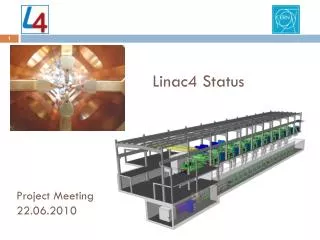
Linac4 layout Normal-conducting linear accelerator, made of: Pre-injector (source, magnetic LEBT, 3 MeV RFQ, chopper line) Three types of accelerating structures, all at 352 MHz (standardization of components). Beam dump at linac end, switching magnet towards transfer line to PSB. • No superconductivity (not economically justified in this range of b and duty cycles); • Single RF frequency 352 MHz (no sections at 704 MHz, standardised RF allows considerable cost savings) ; • High efficiency, high reliability, flexible operation → 3 types of accelerating structures, combination of PMQ and EMQ focusing.
Linac4 – The challenges • Low-energy section: ion source, RFQ, chopping generation of low-emittance intense H- beams, transport and emittance preservation through LEBT and RFQ, efficient transport and chopping • Accelerating structures design prototyping and construction of reliable high efficiency RF structures • Linac beam dynamics emittance preservation, low loss design for possible high-duty operation • PSB injection 4-ring stripping, beam optics • Reliability benchmark: present availability of Linac2 is 98.5%!
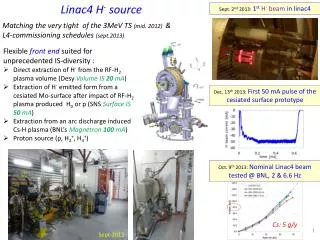
Linac4 – Low energy test stand 3 MeV TEST STANDfor early characterization of low-energy section; will be moved to Linac4 in 2013 • Ion source and LEBT completed and under test; • RFQ in construction; • Chopping line completed, tested without beam; • LEP klystron and modulator installed and tested. • Complete beam diagnostics line being assembled. • Beam tests with RFQ from beginning 2012
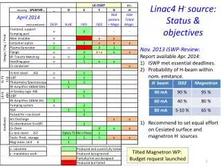
Problems with the H- source • 2005: decision to build an RF Volume source based on the DESY design: • - no resources for an internal development; • - DESY source had high reliability (external antenna, Cesium-free); • - higher extraction voltage + improvements to RF generator and matching to achieve higher current: 45 kV, 100 kW for 80 mA (DESY: 35 kV, 30 kW, 30 mA). • June 2009: source started in the “3 MeV test stand”. Extensive measurements at 35 kV. • From May 2010: increase extraction to 45 kV but severe sparking forbids operation. • Reason: intense electron beam co-extracted with the H- melts the e¯ dump (up to >200 kW instantaneous power in e- beam!). Vaporization (and destruction) of the dump induces sparking. • DESY had less electrons (with less voltage) and more H-. A “chemical” reason? extraction electrode
Revised source program ? 2 test stands, B.357: ion source (+LEBT, diagnostics) B.152: RFQ and chopper testing Extend and improve the source test stand in Bld. 352 (ex-SPL source test stand). Build quickly an improved version of the DESY RF source for L4 commissioning. Build and optimize a Cesiated RF source for L4 2nd part of commissioning and operation. Study (and build) a magnetron-type source to go to high currents – if needed.
The Linac4 RFQ Energy 3 MeV, length 3m, 3 section of 1 m each. Brazed 4-vane design with simplified shape and cooling, for max. duty cycle 10%. Construction entirely done at CERN: machining, metrology, brazing (horizontal). CEA (F) contribution for RF design and measurements. Status: Modules #1 and #2 completed, Module #3 ready for 2nd and last brazing. Programme: RF tests October 2011, conditioning November/December 2011, first beam end 2011. module #3 module #1
“chopping”: removing microbunches (150/352) to adapt the 352MHz linac bunches to the 1 MHz booster frequency Chopping dump Match to the DTL Chop Match from the RFQ beam Emittance increase 20-30%
2.84 ns Chopper line layout Length 3.6 m Already completed, installed in the test stand and tested without beam. Chopper: 2 meander-line structures on ceramic substrate. PSB injection scheme (with energy ramping)
Linac4 – Drift Tube Linac • 3-50 MeV, 3 tanks. • New CERN design, tested on a prototype (1m, 12 drift tubes) at full RF power (10% duty cycle). • Main features: drift tubes rigidly mounted on a girder, with special mounting mechanism, only metallic joints and no adjustment. Tank in Cu-plated stainless steel. Permanent Magnet Quadrupoles in vacuum. • Construction started (DTs with ESS-Bilbao). • Tank1 ready for tests at beginning 2012.
Linac4 – Cell-coupled DTL • 50-100 MeV, 7 modules of 3 tanks each. • New design, tested on a prototype (2 tanks, 4 drift tubes) at full RF power (10% duty cycle). • Main features: Focusing by PMQs (2/3) and EMQs (1/3) external to drift tubes. Short tanks with 2 drift tubes connected by coupling cells. • Construction started at VNIITF (Snezinsk) and BINP (Novosibirsk) in January 2010. • Module#1 and #2 completed, under low-power tests at BINP. To be delivered to CERN for testing end 2011. Structure used for the first time in a particle accelerator !
Linac4 – Pi-Mode Structure Posters TUPS100 - MOPC055 • 100-160 MeV, 12 tanks of 7 cells each. • Tank #1 (pre-series) completed and RF conditioned to 1.25 times the design voltage. • Main features: Focusing by external EMQs, tanks of 7 cells in pi-mode. Full-Cu elements, EB-welded. • Construction started (2011) in collaboration with Soltan Institute (Warsaw) and FZ Julich. Structure used for the first time in a proton accelerator !
45 keV 3 MeV 50 MeV 100 MeV 160 MeV H - PIMS CCDTL RFQ DTL transfer line to PSB chopper line LEBT source 80 m Linac4 – External Contributions Network of agreements to support Linac4 construction. Relatively small fraction of the overall budget, but access to specialized manpower and share of information with other teams. Integration at the component level. RFQ RF design, RF amplifiers, modulator construction (French Special Contribution). Prototype modulator, waveguide couplers, alignment jacks from India. Movable tuners and DTL prototype from Italy. Chopper line built in a EU Joint Research Activity. Collaboration agreement with Soltan Institute (Poland) for PIMS construction. Construction of CCDTL in Russia, via an ISTC Project. Participation of ESS-Bilbao in DTL construction.
Requirements for Linac4 current • Linac4 design 400 ms pulse and 40 mA current correspond to 1014 ppp (twice present ISOLDE with some additional margin). • After connection of Linac4 to the PSB, Linac4+PSB is required to provide the present nominal beams. It is expected to reach the goal for LHC 1-2 years after connection; there are no clear commitments to ISOLDE. • In order to gain some more margin, the maximum Linac4 pulse has been recently extended to 600 ms. • With linac current 20 mA → present beams in PSB + full intensity LHC beam with 40 turns injection. • With linac current 40 mA → maximum ISOLDE beam + full intensity LHC beam with 20 turns injection.
Requirements for Linac4 emittance • Design transverse emittance from ion source 0.25 p mm mrad (rms) • Design transverse emittance at PSB input 0.4 p mm mrad (rms) • We risk to need compromising between current and emittance… Maximum acceptances (no errors, zero current) RFQ : 0.55 p mm mrad Chopper : 0.4 p mm mrad DTL : 0.8 p mm mrad (comparable for other accelerating structures, larger for the transfer line) The PSB can accept a somehow larger emittance
Linac4 – schedule Building delivery 2012/13: Accelerator installation 2011: Infrastructure installation 2013/14: Commissioning
Linac4 commissioning schedule Start of beam commissioning (3MeV): May 2013 End of beam commissioning (160 MeV): April 2014 (version November 2010) 5 commissioning stages: (on intermediate dumps) 3 MeV 10 MeV 50 MeV 100 MeV 160 MeV Connection to the PSB during a long (min. 7 months) LHC shut down after 2014.