Final FED Progress Report CMS Tracker Week 9th April 2003
Final FED Progress Report CMS Tracker Week 9th April 2003. FED FED-PMCs Status. Production of additional 40 FED-PMCs for Module Test setups. Identical to previous Mk3 cards. Some components on last time buy (Xilinx 4036 FPGAs.) PCBs are manufactured. Assembly is in progress.

Final FED Progress Report CMS Tracker Week 9th April 2003
E N D
Presentation Transcript
Final FEDProgress Report CMS Tracker Week9th April 2003
FEDFED-PMCs Status • Production of additional 40FED-PMCs for Module Test setups. • Identical to previous Mk3 cards. • Some components on last time buy (Xilinx 4036 FPGAs.) • PCBs are manufactured. • Assembly is in progress. • Test and deliver in batches of 6-10. • Expect to Start deliveries in June. • Expect to Complete deliveries in July.
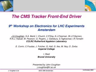
FEDFinal FED JTAG “OptoRx” VME64x CFlash 9U FEDv1 34 x FPGAs 96 channels 2 PCBs assembled & now under test: ser001 at Imperial ser002 at RAL Memories Analogue Power TTC FE Module “Primary” Side
FEDFE Module • N.B. OptoRx is a mechanical sample & not soldered... OpAmps Dual ADCs Delay FPGAs “OptoRx” Test Connector Duplicated on Secondary Side “Primary” Side Front-End Module = 12 channels
FED Progress up to end Q1/03... • 2 FEDv1 pcbs were assembled in January (without OptoRx). • Started with following preliminary tests done at RAL: • Power sequencing. • JTAG Boundary Scan (automated IC connection tests ; passed ok.) • FPGA Configuration (>30 devices) from cable and System ACE Compact-Flash card. • FE Module analogue Electrical tests using Electrical Cross-Point switch card. • (NB no VME readout yet, so data is captured in FPGA using Xilinx Chip-Scope embedded logic analysers read out via cable.) • Digital tests with simple “Test Firmware” loaded in FPGAs.
FED Cross-Point Switch Electrical Test card Cross Point Switch (AD8116) “plug on” test card Electrical tests only Multi-channel Needs external signal generator(s) Sits over OptoRx location (pre OptoRx assembly.) 3 Inputs FED Test Connector
FED Early Electrical Data in FEDv1 sine input (1 MHz) via Cross-Point Switch test card to 12 channels Chip-Scope logic analyser capture 10 bit-raw data on 12 channels in FE FPGA ADC count preliminary first 100 (of 4k) samples @ 40 MHz
FED Progress up to end Q1/03... • 2 OptoRx assembled on ser 001 in March • Ser 001 now at Imperial for detailed characterisation studies of FED with Optical inputs (using Opto Test card Mk1). • Ser 002 kept at RAL for Firmware development / Digital tests. • Collaborative effort in UK between RAL and Imperial (with assistance from Brunel.)
FED Opto-Test card Mk1 Sequence control logic Sequence storage Analogue section VME interface logic DAC Amplification+cm Analogue opto-tx Opto Test Card Mk1 max 3 channels pattern generator (see 96 channel Mk2 card)
FED First Optical Data in FEDv1 “APV frame” pattern on single channel Chip-Scope logic analyser capture 10 bit-raw data ADC count preliminary samples @ 40 MHz unsynchronised clocks
FED Progress up to end Q1/03... • 2 OptoRx assembled on ser 001 in March • Ser 001 just arrived at Imperial for FED detailed characterisation studies with Optical inputs. • Ser 002 kept at RAL for Digital function / Firmware tests. • Collaborative effort in UK between RAL and Imperial (with assistance from Brunel.) • FEDv1 Testing is progressing well… • No “show stoppers” yet for using FEDv1 pcb for Large Scale Assembly tests. • ...but still a lot more to do.
FED Project Targets • FED Project aiming to satisfy 2 targets in next 12 months: • I) FEDs for Large Scale Assembly (LSA) tests: • “July ‘03 (2?) / end ‘03 (2) / beg ‘04 (2) / mid ‘04 (6)” • 96 chan Opto FED essential • only need to provide restricted FED functionality • assumes we can use existing design FEDv1 pcbs • II) FED Pre-Production Manufacture: Q1-2/04 • to stay on final CMS installation schedule • need to demonstrate full FED functionality • assumes new design iteration FEDv2pcbs
FEDLarge Scale Assembly Test Requirements 2003 • Paraphrasing from note of Piero Verdini... • “To Readout Virgin Raw Data formatted as DAQ events via VME in response to TTC trigger and clock.” • Need 96 OptoRx chans. Trigger & Readout rates are not critical. • Functionality • Does require: • Scope Mode and Software Triggers for set up. • Controls from VME for run mode, clock source, clock skew, OptoRx offsets (with readback.) • VME Event buffer with standard DAQ events. Counters for triggers & errors. • System ACE loading, Clock/Trig/Resets on TTC Chan A, Hardware throttle output. • FED delivered as a Package including Software Library to drive the Firmware. • Does not require: • S-LINK readout, Clustering mode, Spy Channel, TTC chan B, TCS (but maybe simple throttle), DAC control, pedestal/threshold data, System ACE interface, VME64x config EPROM…, VME Interrupts, Temp chip control…
FEDPre-Production FEDv2 • Does require : • S-LINK readout, Clustering mode, Spy Channel, TTC chan B, TCS (but maybe simple throttle), DAC control, pedestal/threshold data, System ACE control and in situ-programming, VME64x config EPROM…, VME Interrupts, Temp chip control… • Tested with up to 20 FEDs in a crate. • All operating at target Trigger Rate of 100 kHz! • … FEDv1 has been designed for this. • Assumption: have to demonstrate full functionality before pre-production FEDv2 (Q1-2/2004.)
CMS Tracker FED Schedule Production & Installation Design Test Pre-Pro FEDv1 (20) FEDv2 (20) FEDv3 (500) • FED x 450 installation at CERN expected to start Q3 2005
FEDFirmware Status: Ready to start installing Final Designs on FED... Delay FPGA: Final version synthesised and under test. FE FPGA: Final version synthesised and “ready” for test. BE FPGA: Data path up to QDR filling synthesised and ready for test. TTC chan A interface implemented. Read path to VME in progress incl DAQ formatting. VME FPGA: External VME cycles tested. Serial comms to BE close to test. To do... parallel link to BE incl. readout interface. Steps towards providing Module Test functionality...
FED FPGAs Delay x 24 FE x 8 VME x 1 BE x 1
FEDv1 Firmware Subtasks System ACE EPROM VME FPGA Ed EPROM System ACE VME Bus Temp VME Opto Rx DAC ADC Opto Rx DAC I2C ADC Clocks Serial Comms VME LINK Clocks Serial Comms Regs Clocks Serial Comms Regs Input Data Data Header Mode Header Mode Cluster Mode BE FPGA Saeed Input FIFOs DELAY FPGA x 3 x 8 Scope Mode Output Scope Mode Serial Comms Regs VME Link Ed External Devices Control S-LINK S-LINK FE FPGA x 8 Bill / Ivan Headers Throttle Trigger Implementation in progress Input Simulated QDR Write QDR Read TTC chanA TTCrx Control Ed, John, Matt Tested on FED Chan B QDRs Not needed tilll FEDv2 Data Saeed, Ivan, Emlyn
FEDFirmware Tasks in Q2/03 • Load Final Delay FPGA design. Test DDR to FE FPGA using ChipScope. • Test Serial Comms and Readback: From VME -> BE -> FE -> Delay FPGA • Tests OptoRx controls, ADC clock skew. Requires software. • VME end nearly ready. BE take receiver block from FE design. Provide simple register map and test with software. (Later extend to other controls eg to test clock skewing.) NB Uses Final design of FE, Delay and VME. Test design in BE. • Load Final FE FPGA design. Test DDR inputs, Scope Mode and FIFO outputs. • Meanwhile Test Final BE design writing to QDR. Inputs from FE FPGA in Scope Mode. • Extend BE to test QDR readout to VME. • Add Event/Header formatting for readout. • Test parallel link from BE to VME and readout protocol. Readout via CPU.
FEDFirmware Tasks in Q2/03 • Test Readout interfacetoCPU, poll on VME buffer with register for event length. Software needed. • Use TTC to provide ext clock and trigger. Mostly implemented. But need TTC VME cards to do this test. Need clock and trigger select logic. • Test Final FEVirgin Raw data mode (header finding.) Need APV frame generator (OptoTest Card?) Add synch clock and trigger inputs (TTC or backplane?). Need clock and trigger select logic. • Add Control registers & Counters for nr triggers, (resets), errors…. In BE read by VME.
FEDDelivery Schedule ‘03 • We have 18 OptoRx in hand. Lots more coming in June? • We have 4 extra pcbs in hand. We have necessary components in hand. • Put 8 OptoRx on ser001 in May. • Put 2 OptoRx on ser002 in May. • Assemble another 4 PCBs without OptoRx in May. • We are on schedule to deliver1 FED (ser001) for LSA Tests by beginning of September. • Delivery of 2nd FED (ser002) Q4 2003? • Then further FEDv1’s according to schedule provided... “end ‘03 (2) / beg ‘04 (2) / mid ‘04 (6)” • Availability of LHC crates in UK. (May?) • Other Critical tests for FEDv2 Q3-4… • E.g. S-LINK “direct” tests with FED Kit.
FEDLarge Scale Assembly Setup Assumptions • Assumptions: • Use 9U VME64x crates (LHC crates available for UK tests in May.) • Clock and Trigger arrives on standard TTC Opto cable (on TTC chanA.) • Sync/Bx counters Reset by ‘101’ on chanA. • Hardware Throttle signal level on back-plane pin? • Comments: • Caution should be exercised when using a FED that may not be fully characterised to make detailed measurements of other electronics systems. • Basic FED training to be provided (in UK). • Need well defined points of contact between LSA Testers and UK. • Other FED related projects are being undertaken in UK.
FEDOther Projects in UK… Analogue Optical Hybrids (AOHs) • A 96 channel optical driver to test the FED has been designed at Imperial and is now in layout. • It is consists of four 9U VME cards running in parallel, each with 8 AOHs driving 24 optical fibres. • The 24 analogue inputs to the opto hybrids are fed from an analogue cross-point switch. The latter allows an AOH to receive a signal from any one of the three digital to analogue converters or an external source. • A temperature of the AOHs is maintained to ~0.2 °C to keep the laser output stable. 8-way MU optical connectors DACs Clk & Control Cross-point switches Fibre reels
FEDv1 FEDv1 Provisional Memory Map 8 x 8 KB blocks Offset Currently FEDv1 has 64 KB in A32 address space Reserved E000 Using a “poor man’s” Geographic Addressing scheme... Base Address: Bits 21-16 = Slot number E.g. $0011’0000 - 0011’ffff for slot 17 (Nb Doesn’t use VME64x CSR space.) Reserved C000 Reserved A000 • Restrictions in 2003: • A32 Slave only • D32 access only. • Single Access and Block Transfers (no BT to C&S regs) • No Interrupts VME Buffer 8000 Serial Read Back 6000 Serial Commands 4000 Test Memory Block RAMs 2000 Control & Status 0000 Read Only ID
FEDTest Software Software: Up to now only peek & poke program to VME from Linux. Good enough for really basic firmware tests. But need to integrate FED software into the XDAQ system. And we would like some easy (GUI driven) to use compatible test software. Need FED Application Programming Interface API. A list of software functions FED responds to. API to shield users from Basic low level code needed to... 1. Serial string commands to load and read back FE/DelayFPGA registers as described by Bill. Still to add similar commands for BE FPGA registers. 2. Readout routine. Need register map/list.
FEDv1 Event Readout Protocol • Readout (via VME) Formatted Events identical to those sent to S-LINK • Load Parameters e.g. Peds, Clock skews • Set run mode • Select clock and trigger source • Start Run and enable Triggers/Frames • Poll on VME buffer status • Get length of event • Readout the event (in FPGA buffer sized chunks) • (Raw events > FPGA buffer size) • Reset VME buffer status • Repeat until Run stop • Periodically look at local status registers and counters to check everything is OK DAQ Header Tracker Header Formatted FED Data DAQ Trailer Event Formats: Virgin Raw Data. Raw APV frames. *Scope Mode or Software Trigger Both are fixed event sizes within a Run. (*Empty Tracker Header.)
FEDTest Equipment • Cross-Point cards available for electrical inputs. Most useful in Scope modes. • Second Opto Test card Mk1 for RAL (after Easter). Most convenient for APV patterns. Needed for Raw Data (header finding) readout tests with FE FPGA. • Have TTC VME cards in hand at IC and RAL. • FED Kits for S-LINK in hand at IC and RAL. • New PC/VME Interface (SBS optical link card) by Easter? • Standard LHC VME64x Crates in UK by May. • Large number of OptoRx in UK by June.