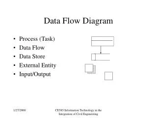
USB: Data Flow
USB: Data Flow. Sukesh Shenoy. USB implementation areas . USB Communication Concepts. Bus Topology Communication Flow Models Bus Access Management Special Consideration for Isochronous Transfers. Bus Topology. There are four main parts to USB Bus topology Host and Devices


USB: Data Flow
E N D
Presentation Transcript
USB: Data Flow Sukesh Shenoy
USB Communication Concepts • Bus Topology • Communication Flow Models • Bus Access Management • Special Consideration for Isochronous Transfers
Bus Topology There are four main parts to USB Bus topology • Host and Devices • Physical Topology • Logical Topology • Client Software-to-function Relationships
Physical Topology • USB elements connected via a tiered star topology. • Connections are provided by special USB devices known as hubs. • Hub provides attachment points knows as ports.
Logical Topology • The host communicates with each logical device as if it were directly connected to the root port.
Client Software-to-function Relationships • Client software for USB functions must use USB software programming interfaces to manipulate their functions • Client software should be independent of other devices that may be connected to the USB.
USB Communication Flow • The USB provides a communication service between software on the host and its USB function. • Software on the host communicates with a logical device via a set of communication flows. • Communication flows are carried over pipes between endpoints and host side memory buffers.
Device End points • Terminus of a communication flow • Each USB device consists of a set of independent device end points. • Each end point is identified by an end point number. • Each end point has a device determined direction of data flow. • Combination of end point number and direction allow an end point on a device to be uniquely referenced. • An end point determines the transfer type between the client software and the end point End point zero requirements • This requirement needs to be satisfied for the USB system software to initialize and generically manipulate the logical device • The endpoints with endpoint number zero are always accessible once a device is attached, powered, and has received a bus reset. Non-End point zero requirements • These end points cannot be used until the device is configured.
Pipes • A USB pipe is an association between an endpoint on a device and software on the host • Pipes represent the ability to move data between software on the host via a memory buffer and an endpoint on a device. • There are two mutually exclusive pipe communication modes: Stream: Data moving through a pipe has no USB-defined structure. Data flows in at one end of a stream pipe and out the other end in the same order. Stream pipes are always unidirectional in their communication flow. Support bulk, isochronous and interrupt transfer types. Message: Data moving through a pipe has some USB-defined structure. Message pipes allow communication flow in both directions, although the communication flow may be predominately one way. Support control transfer type.
Bus Access for Transfers • Data transfer between the host and a USB device requires some use of the USB bandwidth. • The process of assigning bus bandwidth to devices is called transfer management. The key concepts related to bus access: • Transfer Management • Transaction Tracking • Bus Time • Device/Software Buffer Size • Bus Bandwidth Reclamation
Transfer management Transfer management involves several entities that operate on different objects in order to move transactions over the bus: • Client Software: Consumes/generates function-specific data to/from a function endpoint via calls and callbacks requesting IRP with the USBD interface. • USB Driver (USBD): Converts data in client IRP to/from device endpoint via calls/callbacks with the appropriate HCD. • Host Controller Driver (HCD): Converts IRP to/from transactions (as required by a Host Controller implementation) and organizes them for manipulation by the Host Controller. • Host Controller: Takes transactions and generates bus activity via packets to move function-specific data across the bus for each transaction. Transfer Tracking • Host controller has access to the transaction list (stores information regarding pending transactions). • Host controller also provides information regarding status of each transaction (done, pending, halted, etc) • The Host Controller uses some implementation-dependent representation to track what packets to transfer to/from what endpoints at what time or in what order.
Calculating bus transaction times • USB system software needs to calculate the bus time required for each transaction. • Bus time is based on the maximum packet size; dependent on the transfer type Calculating buffer sizes in functions and software • Client software and functions both need to provide buffer space for pending data transactions awaiting their turn on the bus. • If more than one transaction request is pending for a given endpoint, the buffering for each transaction must be supplied. Bus bandwidth reclamation • Bus transmission time is dependent on the transfer types. • Bus transmission time is a calculated constant. • However in actual scenario during each transaction there will be some bus time remaining. Therefore to use bandwidth efficiently, transfer types such as control and bulk maybe used. This is called bus bandwidth reclamation.
Special considerations for isochronous transfers • Transmitter and receiver must be time and data synchronized to deliver datacorrectly. • Time in USB is represented by three clocks: Sample Clock: This clock determines the natural data rate of samples moving between client software on the host and the function. Bus Clock: 1 kHz frequency on full-speed segments and 8 kHz frequency on high speed segments of the bus and is indicated by the rate of SOF packets on the bus. Service Clock: This clock is determined by the rate at which client software runs to service IRP that may have accumulated between executions. • Synchronization of the above mentioned clocks is necessary for correct data delivery. • If transmission errors occur then the receiver reports the errors to the function and appropriate corrective measures are taken.