Download
1 / 27
280 likes | 415 Vues
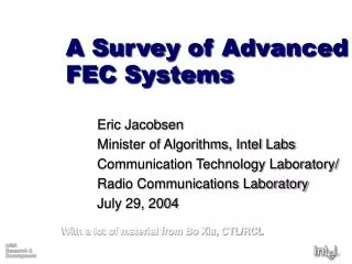
A Survey of Advanced FEC Systems. Eric Jacobsen Minister of Algorithms, Intel Labs Communication Technology Laboratory/ Radio Communications Laboratory July 29, 2004. With a lot of material from Bo Xia, CTL/RCL. Outline. What is Forward Error Correction?

E N D
A Survey of Advanced FEC Systems Eric Jacobsen Minister of Algorithms, Intel Labs Communication Technology Laboratory/ Radio Communications Laboratory July 29, 2004 With a lot of material from Bo Xia, CTL/RCL
Outline • What is Forward Error Correction? • The Shannon Capacity formula and what it means • A simple Coding Tutorial • A Brief History of FEC • Modern Approaches to Advanced FEC • Concatenated Codes • Turbo Codes • Turbo Product Codes • Low Density Parity Check Codes
2 fundamental ways to increase data rate Information Theory Refresh The Shannon Capacity Equation C = W log2(1 + P/ N) Channel Bandwidth (Hz) Transmit Power Noise Power Channel Capacity (bps) C is the highest data rate that can be transmitted error free under the specified conditions of W, P, and N. It is assumed that P is the only signal in the memoryless channel and N is AWGN.
A simple example A system transmits messages of two bits each through a channel that corrupts each bit with probability Pe. Rx Data = { 00, 01, 10, 11 } Tx Data = { 00, 01, 10, 11 } The problem is that it is impossible to tell at the receiver whether the two-bit symbol received was the symbol transmitted, or whether it was corrupted by the channel. Tx Data = 01 Rx Data = 00 In this case a single bit error has corrupted the received symbol, but it is still a valid symbol in the list of possible symbols. The most fundamental coding trick is just to expand the number of bits transmitted so that the receiver can determine the most likely transmitted symbol just by finding the valid codeword with the minimum Hamming distance to the received symbol.
Continuing the Simple Example A one-to-one mapping of symbol to codeword is produced: Symbol:Codeword 00 : 0010 01 : 0101 10 : 1001 11 : 1110 The result is a systematic block code with Code Rate R = ½ and a minimum Hamming distance between codewords of dmin = 2. A single-bit error can be detected and corrected at the receiver by finding the codeword with the closest Hamming distance. The most likely transmitted symbol will always be associated with the closest codeword, even in the presence of multiple bit errors. This capability comes at the expense of transmitting more bits, usually referred to as parity, overhead, or redundancy bits.
Coding Gain The difference in performance between an uncoded and a coded system, considering the additional overhead required by the code, is called the Coding Gain. In order to normalize the power required to transmit a single bit of information (not a coded bit), Eb/No is used as a common metric, where Eb is the energy per information bit, and No is the noise power in a unit-Hertz bandwidth. … … The uncoded symbols require a certain amount of energy to transmit, in this case over period Tb. The coded symbols at R = ½ can be transmitted within the same period if the transmission rate is doubled. Using No instead of N normalizes the noise considering the differing signal bandwidths. Uncoded Symbols Coded Symbols with R = ½ … … Time Tb
Coding Gain and Distance to Channel Capacity Example Uncoded “Matched-Filter Bound” Performance These curves Compare the performance of two Turbo Codes with a concatenated Viterbi-RS system. The TC with R = 9/10 appears to be inferior to the R = ¾ Vit-RS system, but is actually operating closer to capacity. Capacity for R = 3/4
FEC Historical Pedigree 1970 1950 1960 Shannon’s Paper 1948 Early practical implementations of RS codes for tape and disk drives Hamming defines basic binary codes Gallager’s Thesis On LDPCs Berlekamp and Massey rediscover Euclid’s polynomial technique and enable practical algebraic decoding BCH codes Proposed Viterbi’s Paper On Decoding Convolutional Codes Reed and Solomon define ECC Technique Forney suggests concatenated codes
FEC Historical Pedigree II 2000 1980 1990 Ungerboeck’s TCM Paper - 1982 LDPC beats Turbo Codes For DVB-S2 Standard - 2003 RS codes appear in CD players Berrou’s Turbo Code Paper - 1993 First integrated Viterbi decoders (late 1980s) Renewed interest in LDPCs due to TC Research Turbo Codes Adopted into Standards (DVB-RCS, 3GPP, etc.) TCM Heavily Adopted into Standards
Block Codes Generally, a block code is any code defined with a finite codeword length. Systematic Block Code If the codeword is constructed by appending redundancy to the payload Data Field, it is called a “systematic” code. DataField Parity Codeword The “parity” portion can be actual parity bits, or generated by some other means, like a polynomial function or a generator matrix. The decoding algorithms differ greatly. The Code Rate, R, can be adjusted by shortening the data field (using zero padding) or by “puncturing” the parity field. Examples of block codes: BCH, Hamming, Reed-Solomon, Turbo Codes, Turbo Product Codes, LDPCs Essentially all iteratively-decoded codes are block codes.
Convolutional Codes Convolutional codes are generated using a shift register to apply a polynomial to a stream of data. The resulting code can be systematic if the data is transmitted in addition to the redundancy, but it often isn’t. This is the convolutional encoder for The p = 133/171 Polynomial that is in very wide use. This code has a Constraint Length of k = 7. Some low-data-rate systems use k = 9 for a more powerful code. This code is naturally R = ½, but deleting selected output bits, or “puncturing” the code, can be done to increase the code rate. Convolutional codes are typically decoded using the Viterbi algorithm, which increases in complexity exponentially with the constraint length. Alternatively a sequential decoding algorithm can be used, which requires a much longer constraint length for similar performance. Diagram from [1]
Convolutional Codes - II This is the code-trellis, or state diagram of a k = 2 Convolutional Code. Each end node represents a code state, and the branches represent codewords selected when a one or a zero is shifted into the encoder. The correcting power of the code comes from the sparseness of the trellis. Since not all transitions from any one state to any other state are allowed, a state- estimating decoder that looks at the data sequence can estimate the input data bits from the state relationships. The Viterbi decoder is a Maximum Likelihood Sequence Estimator, that estimates the encoder state using the sequence of transmitted codewords. This provides a powerful decoding strategy, but when it makes a mistake it can lose track of the sequence and generate a stream of errors until it reestablishes code lock. Diagrams from [1]
Concatenated Codes A very common and effective code is the concatenation of an inner convolutional code with an outer block code, typically a Reed-Solomon code. The convolutional code is well-suited for channels with random errors, and the Reed-Solomon code is well suited to correct the bursty output errors common with a Viterbi decoder. An interleaver can be used to spread the Viterbi output error bursts across multiple RS codewords. Data RS Encoder Interleaver Conv. Encoder Channel Viterbi Decoder Code Inner Outer Code Data De- Interleaver RS Decoder
Concatenating ConvolutionalCodes Parallel and serial Data CC Encoder1 Interleaver CC Encoder2 Channel Viterbi/APP Decoder Serial Concatenation Data De- Interleaver Viterbi/APP Decoder Data Data Channel Viterbi/APP Decoder Combiner CC Encoder1 De- Interleaver Viterbi/APP Decoder Interleaver CC Encoder2
Iterative Decoding of CCCs Rx Data Viterbi/APP Decoder Interleaver Data De- Interleaver Viterbi/APP Decoder Turbo Codes add coding diversity by encoding the same data twice through concatenation. Soft-output decoders are used, which can provide reliability update information about the data estimates to the each other, which can be used during a subsequent decoding pass. The two decoders, each working on a different codeword, can “iterate” and continue to pass reliability update information to each other in order to improve the probability of converging on the correct solution. Once some stopping criterion has been met, the final data estimate is provided for use. These Turbo Codes provided the first known means of achieving decoding performance close to the theoretical Shannon capacity.
MAP/APP decoders • Maximum A Posteriori/A Posteriori Probability • Two names for the same thing • Basically runs the Viterbi algorithm across the data sequence in both directions • ~Doubles complexity • Becomes a bit estimator instead of a sequence estimator • Optimal for Convolutional Turbo Codes • Need two passes of MAP/APP per iteration • Essentially 4x computational complexity over a single-pass Viterbi • Soft-Output Viterbi Algorithm (SOVA) is sometimes substituted as a suboptimal simplification compromise
Turbo Code Performance II The performance curves shown here were end-to-end measured performance in practical modems. The black lines are a PCCC Turbo Code, and The blue lines are for a concatenated Viterbi-RS decoder. The vertical dashed lines show QPSK capacity for R = ¾ and R = 7/8. The capacity for QPSK at R = ½ is 0.2dB. The TC system clearly operates much closer to capacity. Much of the observed distance to capacity is due to implementation loss in the modem.
Tricky Turbo Codes Repeat-Accumulate codes use simple repetition followed by a differential encoder (the accumulator). This enables iterative decoding with extremely simple codes. These types of codes work well in erasure channels. Repeat Section Accumulate Section Interleaver 1:2 D + R = 1 Inner Code R = 1/2 Outer Code Since the differential encoder has R = 1, the final code rate is determined by the amount of repetition used.
2-Dimensional Data Field Parity Parity Parity Parity Turbo Product Codes Horizontal Hamming Codes The so-called “product codes” are codes Created on the independent dimensions Of a matrix. A common implementation Arranges the data in a 2-dimensional array, and then applies a hamming code to each row and column as shown. The decoder then iterates between decoding the horizontal and vertical codes. Vertical Hamming Codes Since the constituent codes are Hamming codes, which can be decoded simply, the decoder complexity is much less than Turbo Codes. The performance is close to capacity for code rates around R = 0.7-0.8, but is not great for low code rates or short blocks. TPCs have enjoyed commercial success in streaming satellite applications.
Low Density Parity Check Codes • Iterative decoding of simple parity check codes • First developed by Gallager, with iterative decoding, in 1962! • Published examples of good performance with short blocks • Kou, Lin, Fossorier, Trans IT, Nov. 2001 • Near-capacity performance with long blocks • Very near! - Chung, et al, “On the design of low-density parity-check codes within 0.0045dB of the Shannon limit”, IEEE Comm. Lett., Feb. 2001 • Complexity Issues, especially in encoder • Implementation Challenges – encoder, decoder memory
LDPC Bipartite Graph Check Nodes Edges Variable Nodes (Codeword bits) This is an example bipartite graph for an irregular LDPC code.
Iteration Processing 1st half iteration, compute a’s,b’s, and r’s for each edge. Check Nodes (one per parity bit) Edges ai+1 = maxx(ai,qi) bi = maxx(bi+1,qi) ri = maxx(ai,bi+1) ri qi mVn mV = mV0 + Sr’s qi = mV – ri Variable Nodes (one per code bit) 2nd half iteration, compute mV, q’s for each variable node.
LDPC Performance Example LDPC Performance can Be very close to capacity. The closest performance To the theoretical limit ever was with an LDPC, and within 0.0045dB of capacity. The code shown here is a high-rate code and is operating within a few tenths of a dB of capacity. Turbo Codes tend to work best at low code rates and not so well at high code rates. LDPCs work very well at high code rates and low code rates. Figure is from [2]
Current State-of-the-Art • Block Codes • Reed-Solomon widely used in CD-ROM, communications standards. Fundamental building block of basic ECC • Convolutional Codes • K = 7 CC is very widely adopted across many communications standards • K = 9 appears in some limited low-rate applications (cellular telephones) • Often concatenated with RS for streaming applications (satellite, cable, DTV) • Turbo Codes • Limited use due to complexity and latency – cellular and DVB-RCS • TPCs used in satellite applications – reduced complexity • LDPCs • Recently adopted in DVB-S2, ADSL, being considered in 802.11n, 802.16e • Complexity concerns, especially memory – expect broader consideration
Cited References [1] http://www.andrew.cmu.edu/user/taon/Viterbi.html [2] Kou, Lin, Fossorrier, “Low-Density Parity-Check Codes Based on Finite Geometries: A Rediscovery and New Results”, IEEE Trans. On IT, Vol 47-7, p2711, November, 2001
Partial Reference List • TCM • G. Ungerboeck, “Channel Coding with Multilevel/Phase Signals”, IEEE Trans. IT, Vol. IT-28, No. 1, January, 1982 • BICM • G. Caire, G. Taricco, and E. Biglieri, “Bit-Interleaved Coded Modulation”, IEEE Trans. On IT, May, 1998 • LDPC • Ryan, W., “An Introduction to Low Density Parity Check Codes”, UCLA Short Course Notes, April, 2001 • Kou, Lin, Fossorier, “Low Density Parity Check Codes Based on Finite Geometries: A Rediscovery and New Results”, IEEE Transactions on Information Theory, Vol. 47, No. 7, November 2001 • R. Gallager, “Low-density parity-check codes”, IRE Trans. IT, Jan. 1962 • Chung, et al, “On the design of low-density parity-check codes within 0.0045dB of the Shannon limit”, IEEE Comm. Lett., Feb. 2001 • J. Hou, P. Siegel, and L. Milstein, “Performance Analysis and Code Optimisation for Low Density Parity-Check Codes on Rayleigh Fading Channels” IEEE JSAC, Vol. 19, No. 5, May, 2001 • L. Van der Perre, S. Thoen, P. Vandenameele, B. Gyselinckx, and M. Engels, “Adaptive loading strategy for a high speed OFDM-based WLAN”, Globecomm 98 • Numerous articles on recent developments LDPCs, IEEE Trans. On IT, Feb. 2001