Download
1 / 37
370 likes | 477 Vues
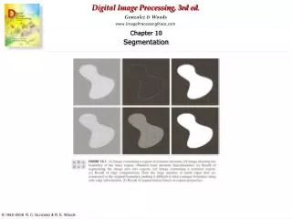
Find the location of the points as follows: w=[-1 -1 -1; -1 8 -1; -1 -1 -1]; g=abs(imfilter ( double(f), w); T=max(g(:)); g=g >=T; imshow(g);. w=[2 -1 -1;-1 2 -1; -1 -1 2]; g=imfilter(double(f), w); imshow(g, []) %Fig.10.4-b g=abs(g( :)); figure, imshow(g, [ ]) % Fig.10-4-e

E N D
Find the location of the points as follows: w=[-1 -1 -1; -1 8 -1; -1 -1 -1]; g=abs(imfilter ( double(f), w); T=max(g(:)); g=g >=T; imshow(g);
w=[2 -1 -1;-1 2 -1; -1 -1 2]; g=imfilter(double(f), w); imshow(g, []) %Fig.10.4-b g=abs(g(:)); figure, imshow(g, [ ]) % Fig.10-4-e T=max(g (: )); G=g >= T; figure, imshow(g, [ ]) % Fig.10-4-f
The image Gradient and its properties • The total of choice for finding edge strenth and direction at location (x,y) of an image, f, is the gradient, denoted by f, and defined as the vector
The image Gradient and its properties • Magnitude (length) of vector f, denoted as M(x,y) • The direction of the gradient vector is given by the angle α(x,y)
IPT’s function edge provides several derivative estimators. For some of these estimators, it is possible to stecify whether thye edge detector is sensitive to horizontal or vertical edges or to both. The general sytax for this function is [g, t]= edge (f, ‘method’ , parameters) Where f is the input image, method is one of the approaches listed in Table and parameters are additional parameters explained later.
The general calling syntax for the Sobel detector is [g, t] = edge (f, ‘sobel’ , T , dir) where T is a specified threshold, and dir specifies the preferred direction of the edges detected: ‘horizontal’, ‘vertical’ , or ‘both’ ( the default). As noted earlier, g is a logical image containing 1s at locations where edges were detecfted and 0s elsewhere.
The Prewitt edge detector uses the masks in Fig.10.14 to approximate digitally the first derivatives Gx and Gy. It’s general calling synax is [g,t]=edge(f,’prewitt’, T, dir) the parameters of this function are identical to the Sobel parameters.
Marr-Hildreth edge detector Marr and Hildreth argued that (1) intensity changes are not independent of image scale and so their detection requires the use of operators different sizes and (2) that a sudden intensity change will give rise to a peak or trough in the first derivative or, equivalently, to zero crossing in the second derivative. More Advanced Techniques for Edge Detection
Marr-Hildreth edge detector • Marr and Hildreth argued that the most satisfactory operator fulfilling these conditions is the filter 2G where, 2 is the Laplacian operator, and G is the 2-D Gaussian function
The general calling syntax for the LoG detector is; [g,t]= edge (f, ‘log’, T, sigma) where sigma is the standard deviation and the other parameters are explained previously.
Zero Crossing Detector: This detector is based on the same concept as the LoG method, but the convolution is carried out using a specified filter function, H. The calling syntax is [g,t]= edge(f, ‘zerocross’, T, H) The other parameters are as explained for the LoG detector.