Download
1 / 13
130 likes | 276 Vues
BRIEF OVER VIEW OF THE MINIMUM PERFORMANCE STANDARD FOR ENGINES describes geometry for a fixture loosely representing an aircraft engine nacelle describes process to produce a representation of the current level of safety protecting these spaces

E N D
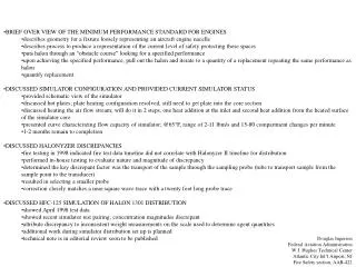
BRIEF OVER VIEW OF THE MINIMUM PERFORMANCE STANDARD FOR ENGINES • describes geometry for a fixture loosely representing an aircraft engine nacelle • describes process to produce a representation of the current level of safety protecting these spaces • puts halon through an “obstacle course” looking for a specified performance • upon achieving the specified performance, pull out the halon and iterate to a quantity of a replacement repeating the same performance as halon • quantify replacement • DISCUSSED SIMULATOR CONFIGURATION AND PROVIDED CURRENT SIMULATOR STATUS • provided schematic view of the simulator • discussed hot plates; plate heating configuration resolved, still need to get plate into the core section • discussed heating the air flow stream; will do it in 2 steps, one heat addition at the inlet and second heat addition from the heated surface of the simulator core • presented curve characterizing flow capacity of simulator; @65°F, range of 2-11 lbm/s and 15-80 compartment changes per minute • 1-2 months remain to completion • DISCUSSED HALONYZER DISCREPANCIES • fire testing in 1998 indicated fire test data timeline did not correlate with Halonyzer II timeline for distribution • performed in-house testing to evaluate nature and magnitude of discrepancy • determined the key discrepant factor was the transport of the sample through the sampling probe (tube to transport sample from the sample point to the transducer) • resulted in selecting a smaller probe • correction closely matches a near-square wave trace with a twenty foot long probe trace • DISCUSSED HFC-125 SIMULATION OF HALON 1301 DISTRIBUTION • showed April 1998 test data • showed recent simulator test pairing; concentration magnitudes discrepant • attribute discrepancy to inconsistent weight measurements on the scale used to determine agent quantities • additional work during simulator distribution set up is planned • technical note is in editorial review soon to be published Douglas Ingerson Federal Aviation Administration W.J. Hughes Technical Center Atlantic City Int’l Airport, NJ Fire Safety section, AAR-422
Dimensions of Various Cross Section for the Nacelle Simulator Ro or H Ri or W area area comment in in in^2 ft^2 A - - - - transition duct B 11 0 380 2.64 exhaust nozzle cross section C 17.5 0 962 6.68 exhaust nozzle cross section D 24 12 1357 9.42 test section aft end F 24 12 1357 9.42 test section middle G 24 12 1357 9.42 test section inlet H 21 6.51 1252 8.69 inlet diffuser middle J 18 1.02 1016 7.06 inlet diffuser entrance K 18 0 1018 7.07 approach duct L 18 0 1018 7.07 straightening grill M 18 0 1018 7.07 straightening grill entrance N 35 35 1225 8.51 tube bank heat exchanger shell P 18 0 1018 7.07 transition duct Q 24 17.5 420 2.92 blower outlet R - - - - supply blower, 3 hp, 22" dia. inlet Douglas Ingerson Federal Aviation Administration W.J. Hughes Technical Center Atlantic City Int’l Airport, NJ Fire Safety section, AAR-422 • Nacelle Simulator Status • Working on heating the core surface • Need to mount hot plates • Need to install two duct heaters at inlet
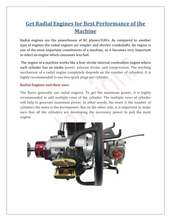
High Bypass Ratio Turbofan Nacelle Simulator Douglas Ingerson Federal Aviation Administration W.J. Hughes Technical Center Atlantic City Int’l Airport, NJ Fire Safety section, AAR-422
High Bypass Ratio Turbofan Nacelle Simulator Douglas Ingerson Federal Aviation Administration W.J. Hughes Technical Center Atlantic City Int’l Airport, NJ Fire Safety section, AAR-422
High Bypass Ratio Turbofan Nacelle Simulator Conceptual Airflow Temperature Profile high temperature condition Temperature low temperature condition ambient temperature condition Length along the simulator heat exchanger blower inlet end core surface heat test section exit entrance to diffuser begin core surface heat fire scenario location Douglas Ingerson Federal Aviation Administration W.J. Hughes Technical Center Atlantic City Int’l Airport, NJ Fire Safety section, AAR-422
High Bypass Ratio Turbofan Nacelle Simulator Comparing Analyzer Response for 5% V/V Halon 1301, Varying Probes Douglas Ingerson Federal Aviation Administration W.J. Hughes Technical Center Atlantic City Int’l Airport, NJ Fire Safety section, AAR-422
High Bypass Ratio Turbofan Nacelle Simulator • Given the compartment ventilation rate (changes/min) in the nacelle is related to that of the analyzer probe. • Variables given are describing : • Q = volumetric flow rate • V = internal volume of probe or nacelle • A = internal cross sectional area of probe or nacelle • L = length of probe or nacelle • x dot = average gas flow velocity in probe or nacelle • f = factor relating the two air change rates • subscript “E”, related to engine nacelle • subscript “T”, related to analyzer probe (tube) • Formulation illustrates air change rates are dependent upon ratios of (neglecting complex flow interactions): • lengths of the probe and nacelle • gas stream velocities • For true “real-time” history, the transducer must see the gas flow at the same velocity the nacelle sees; the factor of {f * [LE / LT]} must approach 1. • One can treat the nacelle event as a source (as in source/sink relationships) because the total sampling volume from the nacelle flow is negligible; the factor {f * [LE / LT]} can be set to approach zero; therefore capturing the event with inconsequential time dilation considerations. Gas Concentration Data Disagreement with Fire Test Data Douglas Ingerson Federal Aviation Administration W.J. Hughes Technical Center Atlantic City Int’l Airport, NJ Fire Safety section, AAR-422
High Bypass Ratio Turbofan Nacelle Simulator The trace from the 1/8”ODx20 ft long probe is approximately a pure time displacement of the near-square wave forms shown. Douglas Ingerson Federal Aviation Administration W.J. Hughes Technical Center Atlantic City Int’l Airport, NJ Fire Safety section, AAR-422
HFC-125 Simulation of a Halon 1301 Distribution, April 1998 Douglas Ingerson Federal Aviation Administration W.J. Hughes Technical Center Atlantic City Int’l Airport, NJ Fire Safety section, AAR-422 High Bypass Ratio Turbofan Nacelle Simulator
HFC-125 Simulation of a Halon 1301 Distribution, April 1998 Douglas Ingerson Federal Aviation Administration W.J. Hughes Technical Center Atlantic City Int’l Airport, NJ Fire Safety section, AAR-422 High Bypass Ratio Turbofan Nacelle Simulator
HFC-125 Simulation of a Halon 1301 Distribution, April 1998 Douglas Ingerson Federal Aviation Administration W.J. Hughes Technical Center Atlantic City Int’l Airport, NJ Fire Safety section, AAR-422 High Bypass Ratio Turbofan Nacelle Simulator
HFC-125 Simulation of a Halon 1301 Distribution, April 1998 Douglas Ingerson Federal Aviation Administration W.J. Hughes Technical Center Atlantic City Int’l Airport, NJ Fire Safety section, AAR-422 High Bypass Ratio Turbofan Nacelle Simulator
HFC-125 Simulation of a Halon 1301 Distribution in the FAA Nacelle Simulator, 20April1999 Douglas Ingerson Federal Aviation Administration W.J. Hughes Technical Center Atlantic City Int’l Airport, NJ Fire Safety section, AAR-422 High Bypass Ratio Turbofan Nacelle Simulator • Halon 1301 curves are translated along the time axis for clarity. • the agent weights transferred to the fire extinguisher was not in accordance with the procedure to correctly simulate Halon 1301 with HFC-125. • Generally agreeable qualitative behavior is still observed