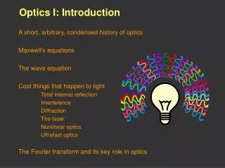
Introduction to Experiments in Optics
Introduction to Experiments in Optics. Short Tutorial on Optics (PowerPoint) Safety & Good working practices A. Lens Imaging (Ray Optics) B. Single-slit diffraction (Wave Optics) . 1 st Yr Laboratory, Physics, Imperial College London. Damzen 09/07. Technological Revolution in Optics.


Introduction to Experiments in Optics
E N D
Presentation Transcript
Introduction to Experiments in Optics Short Tutorial on Optics (PowerPoint) Safety & Good working practices A. Lens Imaging (Ray Optics) B. Single-slit diffraction (Wave Optics) 1st Yr Laboratory, Physics, Imperial College London Damzen 09/07
Technological Revolution in Optics Communication by photons Telephony/data/internet Massive optical data storage CD/DVD Blu-ray disc (25GB) Precision laser machining Laser writing on human hair Photolithography for manufacture of computer chips Laser cutting Medical laser therapy & optical imaging Corrective laser eye surgery 3-D laser imaging of cell
Telescope observations forged our understanding of the Universe Optics, light & vision has been vital for human survival Microscopes revealed a micro-universe Optics has an important place in history Today, Optics remains a key scientific diagnostic technique (e.g. imaging). A new revolution in Optics has emerged with the birth of the laser, fibre optics, integration of optics and electronics, etc..
Particles Waves Light = EM waves Historical debate on nature of light or
Wave-particle duality Quantum Optics Lasers LASER What is Light? - Revisited Stimulated emission Paradoxes in physics (BB radiation/ photoelectric effect) Quantisation of light (photons) E=hn Bohr model of atom Wavefunctions / Probability Diffraction of electrons Planck / Einstein Michelson Maiman (Laser) …
Fundamentals of Optics REFLECTION REFRACTION IMAGING DIFFRACTION INTERFERENCE POLARISATION Continuum of waves Finite no. of waves EM-theory
Safety and Lab-book Practices • Safety • Laser Safety • NEVERLOOK DIRECTLY INTO THE LASER OR POINT LASER AT OTHER PERSONS • Electrical Safety • Trip Hazards Your Laboratory Notebook · DATE, TIME, TITLE OF EXPERIMENT. · CLEAR WRITTEN RECORD AS YOU GO ALONG. · DESCRIBE & DRAW WHAT YOU ACTUALLY SEE.
Lenses –Ray Diagrams and Formulae CONSTRUCTING RAY DIAGRAMS LENS CALCULATIONS Thin lens formula Magnification formula O object; I image s object distance; s’ image distance; f focal length • PRINCIPLE RAYS: (Any 2 are sufficient to construct image) • Ray passing through the centre of the lens is undeviated. • Ray parallel to the optical axis passes through a focal point. • Ray passing towards, or away from, a focal point emerges parallel to the axis. In later lab-work: you’ll explore issues of real lens (e.g. finite aperture; lens aberration)
Before we proceed to first experiment….. • Find a lab-partner & Sit at one of the Optical Set-ups • 1. Open your lab-book and write date and time • 2. Write heading “Introduction to Experiments in Optics” • 3. Write sub-heading: “A. Thin Lens Imaging”
Aligning an Optical Bench • A good rule of optical alignment is to: • place one item at a time on bench (starting at light source) • ensure light propagates parallel to bench (rotate post of light source if necessary) • optical components are centred (by adjusting post height) and • optical components are at right-angles to beam path (by rotating post).
Expt 1.1 Imaging with a Lens 1. Switch on light source (supply at ~ 5V preset, do not adjust) 4. Adjust position of ground-glass screen for sharpest image. Measure s’. 3. Place f=100mm lens at object distance s=150mm. Measure s with ruler from object to lens centre 2. As object place slide of letter L, in slot-holder on light source 5. Measure a dimension of object (hO) and corresponding size in image (hI). Deduce magnification |m|=hI/hO hO hI • Estimate an error for all experimental values measureds, s’, hO, hI.
Errors? 4 measured quantities Experimental measurement Theoretical prediction Why is ss’ >ss? How might you estimate ss’? Calculate the magnification (inc. standard error) for the two methods. Do they agree / are they consistent given the errors?
Experiment 1.2 Measuring focal length of lens 2. Angle mirror so you can see reflected spot of light on object slide. (You may not be able to see this until lens is near its focal length position) 1. Use pin-hole slide as object 3. Measure focal length f by finding the position for minimum reflected spot size Is focal length f=100mm?
B. Wave-Optics : Single-slit Diffraction secondary wavelets Light pattern at any plane z is the sum of secondary wavelets of the unobstructed aperture (including phases) Aperture (width a) causes light to spread (diffraction) a z z Far-field (z>>a2/l)= Fraunhofer diffraction (simpler mathematical form =Fourier Transform) Near-field (z<a2/l) = Fresnel diffraction (complex mathematical form)
Far-field at focal plane of lens Problem: Far-field z>> a2/l may not be convenient for lab bench. Solution: Use lens. Figure 4: The far-field diffracted pattern can be visualised in the focal plane of a lens.
Expt.2 Visual Observation of Single-Slit Diffraction Pattern x 2. Visually observe diffraction pattern of variable slit on white screen placed at focal length of lens 1. Replace white light source by Diode Laser • Note in you lab-book the effect of changing the slit width. • With the central maximum peak of width ~10mm sketch the diffraction pattern (to scale)
Far-field Single-Slit Diffraction Pattern x Positions of zeroes xm = m(lf/a) Is this what you see?
Measurement with a Photo-detector 1. Switch on photodiode power supply and set voltmeter to 200mV setting I0 2. Position central maximum of diffraction pattern to coincide with photodiode slit at centre of its translation stage. You may need to rotate laser and move diffracting slit sideways to achieve this I1 X-1 X1 • Measurements: • Measure voltage of central maximum (V0) and first secondary maximum (V1). • Measure positions of the first minima (X1 and X-1). Hence calculate the slit width using: X1 – X-1 = 2lf/a
Final Comments • It is hoped that this introductory Optics session has given you: • some useful practice in laboratory work (inc. lab notebook and errors) • provided some groundwork for more advanced Optics you will perform in the lab later in the year. • confidence in working in the UG laboratory