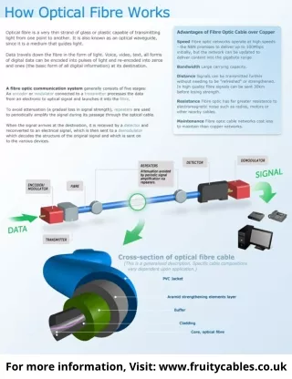
Download
1 / 21
240 likes | 514 Vues
3D Optical Trapping via Tapered Optical Fibre at Extreme Low Insertion Angles . Presentation by: Steven Ross The GERI Weekly Seminar Friday 18 th October 2013 Supervisors: Prof. D. R. Burton, Dr. F. Lilley & Dr. M. F. Murphy.

E N D
3D Optical Trapping via Tapered Optical Fibre at Extreme Low Insertion Angles Presentation by: Steven Ross The GERI Weekly Seminar Friday 18th October 2013 Supervisors: Prof. D. R. Burton, Dr. F. Lilley & Dr. M. F. Murphy General Engineering Research Institute (GERI), Coherent & Electro-Optics Research Group (CEORG), Liverpool John Moores University (LJMU), GERI Building, Byrom Street, Liverpool, L3 3AF, UK. Email: s.ross@2002.ljmu.ac.uk
Introduction • What is optical trapping? • Optical trapping history & basic theory • Optical trapping configurations • Pros & cons of “classical” and fibre systems • Tapered fibre optic tweezers(T-FOT’s) system • Optical fibre insertion angle issues & solutions • Maximum trapping range • Conclusion
What is Optical Trapping? • Exploitation of the forces produced during the interaction between light and matter • Allowing the deflection, acceleration, stretching, compression, rotation and confinement of organic & inanimate material • Ranging in sizes from the microscopic down to the atomic level • Optical forces can be in excess of 100 Pico Newton’s with sub-Nanometre resolution • Excellent force transducers
The Origins of Optical Trapping • 1969 -Arthur Ashkin – Bell Laboratories • Effects of electromagnetic radiation pressure forces on microscopic particles • Witnessed Unusual phenomena • Expected – Particles driven in the direction of the laser beam’s propagation • Unexpected - Particles located at the fringes of the laser beam’s axis were drawn into the high intensity region of the axis
Optical Forces Acting on a Particle Ashkin's initial observations Total forces acting on a particle
Optical Trapping System Configurations Counter propagating laser beams Particle levitation trap
Optical Trapping System Configurations Multiple Optical Tweezers • Dual Optical tweezers • Splitting the beam • Two laser sources • Multiple trap systems • Fast Scanning time shared laser beam • Diffractive optical element (DOE) • Computer generated holographic optical trap’s Single Beam gradient force optical trap – “Optical tweezers”
Pros & Cons of “Classical” and fibre Based System Configurations “Classical” optical tweezers Fibre Based Optical Tweezers Reduced size and build costs No bulk optics required No high (NA) microscope objective required Therefore it can be decoupled from the microscope Optical fibre delivers the trapping laser light to the sample chamber Basic system consists of a laser and an optical fibre Ideal for project design criterion • Very large surface area required to mount the bulk optics • Physically large compared to the miniaturised arena which they were built to serve • Require a high numerical aperture (NA) microscope objective • Expensive • Poor solution for project design criterion
Disadvantages of Fibre Based Optical Trapping Systems Known Fibre Trapping Issues Problem Relating to the Project Requires fixing and manipulation Fibre’s distal end requires shaping to focus the light Requires higher optical powers to reach same level of forces Design criterion requires an insertion angle of ≤ 10° to pass under the atomic force microscope (AFM) head • Optical fibre is a physical entity • The light exiting a Fibre is divergent • Optical trapping efficiency of fibre systems < “classical” systems • Literature suggests that trapping cannot occur at fibre insertion angles below 20°
Atomic Force Microscope (AFM) AFM Head Optical Lever Detection System
3D optical Trapping at 10° Insertion Angle • Initial attempt to trap at a 10° Insertion angle failed at low optical output powers • At extremely high optical output powers in excess of 500 mW 3D optical trapping was observed • Leading to investigations as to why trapping only occurred at high optical output powers at an insertion angle of 10°
Investigation into Trapping Failure at Sub-45° Insertion Angles
Investigation into Trapping Failure at Sub-45° Insertion Angles
Fibre Taper Optimisation for 10° Insertion Angle Optical Trapping Tip 44 Tip 92 Tip 94 Tip 96
Maximum Trapping Range [1] Z. Liu, C. Guo, J. Yang and L. Yuan, “Tapered fiber optical tweezers for microscopic particle trapping: fabrication and application,” Opt. Express 14(25), 12510-12516 (2006)
Conclusion • Brief explanation of optical trapping, its origins, basic theory behind the technique & the various system configurations • Provided an evaluation of the pros & cons for both classical and fibre based systems • Presented T-FOTs a 3D fibre based optical trapping system • Offered a hypothesis for trapping failure at a 10° insertion angle & provided a viable solution for the problem • Discussed the maximum trapping range
Thank You Any Questions?