Download
1 / 21
210 likes | 412 Vues
A Four Rod Compact Crab Cavity for LHC. Dr G Burt Lancaster University / Cockcroft Institute. Cavity Design Team. G Burt (CI-Lancs) B Hall (CI-Lancs) C. Lingwood (CI-Lancs) D. Doherty (CI-Lancs) A. Dexter (CI-Lancs) Clive Hill (STFC) P McIntosh (STFC) H Wang (JLab) B Rimmer (JLab)

E N D
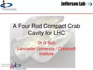
A Four Rod Compact Crab Cavity for LHC Dr G Burt Lancaster University / Cockcroft Institute
Cavity Design Team • G Burt (CI-Lancs) • B Hall (CI-Lancs) • C. Lingwood (CI-Lancs) • D. Doherty (CI-Lancs) • A. Dexter (CI-Lancs) • Clive Hill (STFC) • P McIntosh (STFC) • H Wang (JLab) • B Rimmer (JLab) • L Turlington (Jlab) + CERN (Jochim Tuckmantel, Erk Jensen and Ed Ciapala) on cavity integration
CEBAF separator cavity is: 499 MHz, 2-cell, 8 rods ~λ long 0.3 m diameter, can produce 600kV deflecting voltage (on crest) with 1.5kW input RF power. Qcu is only ~5000 (structure wise), the stainless steel cylinder only takes less than 5% of total loss. The maximum surface magnetic field at the rod ends is ~8.2 mT. Water cooling needed on the rods. If Nb used for this type of cavity, the V is KEKB CC. Microphonics and fabrication issues to be resolved. Initial Studies for a Compact CC
At 400 MHz, and V = 3 MV: single cell (length = 30 cm) R/Q = 700 Ohms Emax = 90 MV/m Bmax = 120 mT 4-Rod Design (2009) • Modification of existing CEBAF 2-rod separator cavity (collaboration with H Wang at JLab): • Has a 10 cm diameter beam-pipe, • Has 40 cm diameter for both frequencies. B fields E fields
Bmax vs. Elliptical Base Further decreases in surface magnetic field can be made by using an elliptical base. Oval breadth allows increase in rod base size without disproportionate increasing interaction with outer can Small breadth leads to field enhancement down the side of the rods
Rod cross-section shape • If the rod is shaped around the beam-pipe a lower peak B field can be obtained as the current is spread over a larger area. • The peak magnetic field also moves to the side of the rods away from the beampipe
Final(ish) Cavity Shape The cavity design includes a 280mm / 230 mm diameter squashing to increase coupling to the LOM when a coupler is included. Cavity fits in all LHC scenarios (84 mm aperture) and meets design gradient. RT/Q=(V(a)2/wU)*(c/wa)2
236 mm 286 mm Final(ish) Cavity Design 408 mm
Variation in Transverse Voltage There is some change in transverse voltage when there are horizontal and vertical offsets.
Four TEM modes + + + - + - - - There are two parallel bar TEM modes, only one interacts with the beam and this is our operating mode + - + + - + + + There are also two co-axial like TEM modes (potential difference between rods and outer can), only one of these interacts with the beam, this is our wrong or lower order mode (W/LOM)
+ - - + Lower Order mode • For the 4 rod cavity the LOM has an R/Q of 120 (which is low considering the R/Q of the crabbing mode. This is because the fields are concentrated close to the walls. • This mode has an azimuthal magnetic field flowing around the outer can which is ideal for loop coupling. LOM coupler reduces the frequency of this mode by up to 20 MHz.
Higher Order Modes We also have some TEM HOMs. As the cavity is compact in the vertical plane most of the TM modes are at higher frequencies, and the TE modes have low shunt impedances. Monopole 3p/4 resonator Dipole 3p/4 resonator
Racetrack Cross section • The fields are weaker far from the rods so a squashed can shape enhances coupling. • A high magnetic field can occur in the gap between the outer can and the rod if the gap is too small. • A racetrack cross section has been shown to be superior to an elliptical shape as it causes less magnetic field enhancement as the gap can be made constant.
Demountable Coaxial coupler • Demountable HOM style coupler based of the LEP design. • Pull-out for coupler provides additional access to cavity for cleaning. • External-Q’s down to 67 have been achieved for 2 couplers, depending on the penetration of the hook into the cavity. • To ensure symmetric fields the couplers can be placed on opposing sides of the can.
Cavity Cleaning • Beam-pipe is large and can be used as access for cleaning. HPR nozzle • Large demountable LOM couplers can also be used for cavity cleaning and/or draining acid.
Input coupler • Position of coupler constrained by space available from rounding on beam-pipe to cavity transition, and space for e-beam welding. Coupler consists of a cut-off waveguide located on beam pipe with a waveguide-to-coax transition to minimise heat leak to room temperature. This design allows the coupler to avoid the opposing beamline.
Multipacting Some multipacting has been found at low E field. Vt ~ 150 kV located on the outer can along the flat surface. Multipacting was also seen at the beam-pipe at 1.5-2.2 MV on limited simulations, similar to results on elliptical cavities. This needs further investigation. Modifications to the beam-pipe may remove this (See Zenghai’s talk last year).
Microphonics studies • FEM studies have begun looking at thermal issues and microphonics. • The first two modes in the rods are at 1.45 kHz and 2.05 kHz. • The outer can fundamental vibration mode is at 674 Hz.
Cavity Prototype • UK have some funding for a cavity prototype in Niobium. • UK and Jlab have significant expertise in cavity measurements and verification. • Beadpull and wire tests could be performed, as well as coupler verification on a preliminary copper cavity. • Vertical cryostat tests will be critical in verifying the cavity concept. • Larry Turlington at Jlab is currently working on the cavity manufacturing methods and dies.
Cavity construction (without couplers) Some components could possible be machined from solid Nb instead Rods x 4 (pressed or hydroformed) Tips may need to be pressed and welded on to taped tubes Beam-pipe (rolled) End caps would be pressed (or machined?) Shell (rolled)
Conclusion • A new cavity shape is proposed for the LHC. • The crabbing TEM mode allows a very transversely compact design. • The compact size does not impact of the cavity fields greatly. • Coupler designs are under investigation. • A prototype is expected to be constructed in 2011/12.