Download
1 / 50
500 likes | 754 Vues
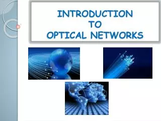
A Brief Introduction to Optical Networks. EE 122, UC Berkeley April 27 & 30, 2001 Gaurav Agarwal gaurav@eecs.berkeley.edu. What I hope you will learn. Why Optical? Intro to Optical Hardware Three generations of Optical Various Switching Architectures Circuit, Packet and Burst

E N D
A Brief Introduction to Optical Networks EE 122, UC Berkeley April 27 & 30, 2001 Gaurav Agarwal gaurav@eecs.berkeley.edu
What I hope you will learn • Why Optical? • Intro to Optical Hardware • Three generations of Optical • Various Switching Architectures • Circuit, Packet and Burst • Protection and Restoration EE122, UC Berkeley
Outline • Why Optical? (Any guesses???) • Intro to Optical Hardware • Three generations of Optical • Various Switching Architectures • Circuit, Packet and Burst • Protection and Restoration EE122, UC Berkeley
Bandwidth: Lots of it • Usable band in a fiber • 1.30m - 1.65m 40 THz • spaced at 100 GHz 400 s per fiber • Link Speeds upto 40 Gbps per • OC-3 155Mbps • OC-768 40Gbps becoming available • Total link capacity • 400 * 40Gbps = 16 Tbps! • Do we need all this bandwidth? EE122, UC Berkeley
Other advantages • Transparent to bit rates and modulation schemes • Low bit error rates • 10-9 as compared to 10-5 for copper wires • High speed transmission • To make this possible, we need: • All-Optical reconfigurable (within seconds) networks • Definitely a difficult task EE122, UC Berkeley
All-Optical Switch* All-Optical Switch* All-Optical Switch* What a path will look like Lasers generate the signal Optical receivers Optical Amplifier * All-optical Switch with wavelength converters and optical buffers EE122, UC Berkeley
Outline • Why Optical? • Intro to Optical Hardware • Three generations of Optical • Various Switching Architectures • Circuit, Packet and Burst • Protection and Restoration EE122, UC Berkeley
Fiber & Lasers • Fiber • Larger transmission band • Reduced dispersion, non linearity and attenuation loss • Lasers • Upto 40Gbps • Tunability emerging • Reduced noise (both phase and intensity) • Made from semiconductor or fiber EE122, UC Berkeley
Optical Amplifiers • As opposed to regenerators • Make possible long distance transmissions • Transparent to bit rate and signal format • Have large gain bandwidths (useful in WDM systems) • Expensive (~$50K) Now: Optical Amps Then: Regenerators EE122, UC Berkeley
1 1 2 OADM 2 3 ’3 3 ’3 Optical Add-Drop Multiplexers • Optical Add-Drop Multiplexer (OADM) • Allows transit traffic to bypass node optically • New traffic stream can enter without affecting the existing streams EE122, UC Berkeley
Optical Switches • Route a channel from any I/P port to any O/P port • Can be fixed, rearrangable, or with converters • MEMS (Micro Electro Mechanical Systems) • Lucent, Optical Micro Machines, Calient, Xros etc. • Thermo-Optic Switches • JDS Uniphase, Nanovation, Lucent • Bubble Switches • Agilent (HP) • LC (Liquid Crystal) Switches • Corning, Chorum Technologies • Non-Linear Switches (still in the labs) EE122, UC Berkeley
MEMS Switches 2-D Optical Switches • Crossbar architecture • Simple Digital Control of mirrors • Complexity O(N²) for full non blocking architecture • Current port count limited to 32 x 32. EE122, UC Berkeley
3D MEMS Switch Architecture 3-D Optical Switches • Analog Control of Mirrors. • Long beam paths (~1m) require collimators. • Complexity O(N) (Only 2N mirrors required for a full non blocking NxN switch) • Lucent Lambda Router : Port 256 x 256; each channel supports upto 320 Gbps. EE122, UC Berkeley
Wavelength Converters • Improve utilization of available wavelengths on links • All-optical WCs being developed • Greatly reduce blocking probabilities 3 2 3 2 WC No converters With converters 1 New request 1 3 1 New request 1 3 EE122, UC Berkeley
Optical Buffers • Fiber delay lines are used • To get a delay of 1msec: • Speed of Light = 3*108 m/sec • Length of Fiber = 3*108 *10-3 m = 300 km EE122, UC Berkeley
Outline • Why Optical? • Intro to Optical Hardware • Three generations of Optical • Various Switching Architectures • Circuit, Packet and Burst • Protection and Restoration EE122, UC Berkeley
E-O Switch O-E-O Switch O-E Switch Generation I • Point-to-point optical links used simply as a transmission medium • Fiber connected by Electronic routers/switches with O-E-O conversion • Regenerators used for long haul Electronic data as the signal Signal received as electronic Regenerators EE122, UC Berkeley
Generation II • Static paths in the core of the network • All-Optical Switches (may not be intelligent) • Circuit-switched • Configurable (but in the order of minutes/hours) • Soft of here EE122, UC Berkeley
IP Router Network IP Router Network IP Router Network NNI UNI Light Path Optical Subnet Optical Subnet Optical Subnet End-to-end path Gen II: IP-over-Optical EE122, UC Berkeley
Peer Model • IP and optical networks are treated as a single integrated network • OXCs are treated as IP routers with assigned IP addresses • No distinction between UNI and NNI • Single routing protocol instance runs over both domains • Topology and link state info maintained by both IP and optical routers is identical EE122, UC Berkeley
Overlay Model • IP network routing and signaling protocols are independent of the corresponding optical networking protocols • IP Client & Optical network Server • Static/Signaled overlay versions • Similar to IP-over-ATM EE122, UC Berkeley
Integrated Model • Leverages “best-of-both-worlds” by inter-domain separation while still reusing MPLS framework • Separate routing instances in IP and ON domains • Information from one routing instance can be passed through the other routing instance • BGP may be adapted for this information exchange EE122, UC Berkeley
Generation III • An All-Optical network • Optical switches reconfigurable in milli-seconds • Intelligent and dynamic wavelength asignment, path calculation, protection built into the network • Possibly packet-switched • Dream of the Optical World EE122, UC Berkeley
Generation III (contd.) • Optical “routers” perform L3 routing • No differentiation between optical and electrical IP domains • Routing decision for each packet made at each hop • Statistical sharing of link bandwidth • Complete utilization of link resources EE122, UC Berkeley
Outline • Why Optical? • Intro to Optical Hardware • Three generations of Optical • Various Switching Architectures • Circuit, Packet and Burst • Protection and Restoration EE122, UC Berkeley
Electronic Network Electronic Network Electronic Network Electronic Network State of the World Today O/E/O E/O E/O O/E/O O/E/O O/E/O O/E/O O/E/O E/O E/O Optical Core EE122, UC Berkeley
View of a E/O node Input Port 1 Input Port 1 O P 1 Optical Link 1 Electrical Optical Input Port 2 Input Port 2 O P 2 Optical Link 2 Input Port 3 O P 3 Input Port 3 O P 4 Optical Link 3 Input Port 4 Input Port 4 O P N-1 O P N Physical View Logical View EE122, UC Berkeley
Electronic Network Electronic Network Electronic Network Electronic Network O/E/O O/E/O O/E/O O/E/O O/E/O O/E/O Optical Circuit Switching OS O/E/O E/O E/O O/E/O OS OS O/E/O OS O/E/O O/E/O OS O/E/O OS E/O E/O Optical Core EE122, UC Berkeley
Electronic Network Electronic Network Electronic Network Electronic Network Optical Circuit Switching O/E/O OS E/O E/O OS O/E/O O/E/O OS O/E/O OS OS O/E/O OS WC O/E/O E/O E/O Optical Core EE122, UC Berkeley
Optical Circuit Switching • A circuit or ‘lightpath’ is set up through a network of optical switches • Path setup takes at least one RTT • Need not do O/E/O conversion at every node • No optical buffers since path is pre-set • Need to choose path • Need to assign wavelengths to paths • Hope for easy and efficient reconfiguration EE122, UC Berkeley
Problems • Need to set up lightpath from source to destination • Data transmission initiated after reception of acknowledgement (two way reservation) • Poor utilization if subsequent transmission has small duration relative to set-up time. (Not suited for bursty traffic) • Protection / fault recovery cannot be done efficiently Example : Network with N switches, D setup time per switch, T interhop delay. Circuit Setup time = 2.(N-1).T + N.D If N = 10, T = 10ms, D = 5ms, setup time = 230 ms. At 20 Gbps, equivalent to 575 MB (1 CD) worth of data ! EE122, UC Berkeley
Optical Packet Switching • Internet works with packets • Data transmitted as packets (fixed/variable length) • Routing decision for each packet made at each hop by the router/switch • Statistical sharing of link bandwidth leads to better link utilization • Traffic grooming at the edges? Optical header? EE122, UC Berkeley
Problems • Requires intelligence in the optical layer • Or O/E/O conversion of header at each hop • Packets are small Fast switching (nsec) • Need store-and-forward at nodes or Deflection Routing. Also store packet during header processing • Buffers are extremely hard to implement • Fiber delay lines • 1 pkt = 12 kbits @ 10 Gbps requires 1.2 s of delay => 360 m of fiber) • Delay is quantized • How about QoS? EE122, UC Berkeley
Multiprotocol Lambda Switching • D. Awduche et. al., “Requirements for Traffic Engineering Over MPLS,” RFC 2702 • Problem decomposition by decoupling the Control plane from the Data plane • Exploit recent advances in MPLS traffic engineering control plane • All optical data plane • Use as a “label” • The on incoming port determines the output port and outgoing EE122, UC Berkeley
OXCs and LSRs • Electrical Network – Label Switched Routers (LSR) • Optical Network – Optical Cross Connects • Both electrical and optical nodes are IP addressable • Distinctions • No merging • No push and pop • No packet-level processing in data plane EE122, UC Berkeley
Optical Burst Switching • Lies in-between Circuit and Packet Switching • One-way notification of burst (not reservation) – can have collisions and lost packets • Header (control packet) is transmitted on a wavelength different from that of the payload • The control packet is processed at each node electronically for resource allocation • Variable length packets (bursts) do not undergo O/E/O conversions • The burst is not buffered within the ON EE122, UC Berkeley
Various OBSs • The schemes differ in the way bandwidth release is triggered. • In-band-terminator (IBT) – header carries the routing information, then the payload followed by silence (needs to be done optically). • Tell-and-go (TAG) – a control packet is sent out to reserve resources and then the burst is sent without waiting for acknowledgement. Refresh packets are sent to keep the path alive. EE122, UC Berkeley
Offset-time schemes • Reserve-a-fixed-duration (RFD) • Just Enough Time (JET) • Bandwidth is reserved for a fixed duration (specified by the control packet) at each switch • Control packet asks for a delayed reservation that is activated at the time of burst arrival • OBS can provide a convenient way for QoS by providing extra offset time EE122, UC Berkeley
ta2(= ts2) ta2(= ts2) to1 ta1 ts1 ts1+ l1 QoS using Offset-Times Assume two classes of service Class 1 has higher priority Class 2 has zero offset time to1 i Time ta1 ts1 ts1+ l1 i Time ta2(= ts2) ts2+ l2 tai = arrival time for class i request tsi = service time for class i request toi = offset time for class i request li = burst length for class i request EE122, UC Berkeley
Comparison EE122, UC Berkeley
Optical MAN Optical MAN Optical MAN Optical MAN Hierarchical Optical Network E/O E/O E/O E/O E/O OS All O All O OS E/O E/O E/O OS OS OS WC E/O E/O E/O E/O All O All O Optical Core E/O E/O E/O E/O EE122, UC Berkeley
Hierarchical Optical Network • Optical MAN may be • Packet Switched (feasible since lower speeds) • Burst Switched • Sub- circuit switching by wavelength merging • Interfaces boxes are All-Optical and merge multiple MAN streams into destination-specific core stream • Relatively static Optical Core • Control distributed to intelligent edge boxes EE122, UC Berkeley
Outline • Why Optical? • Intro to Optical Hardware • Three generations of Optical • Various Switching Architectures • Circuit, Packet and Burst • Protection and Restoration EE122, UC Berkeley
Link vs Path Protection • For failure times, need to keep available s on backup path • Link: Need to engineer network to provide backup • Path: need to do end-to-end choice of backup path EE122, UC Berkeley
Path protection Dedicated (1+1) – send traffic on both paths Dedicated (1:1) – use backup only at failure Shared (N:1) – many normal paths share common backup Link Protection Dedicated (each is also reserved on backup link) Shared (a on backup link is shared between many) Types of Protection EE122, UC Berkeley
Restoration • Do not calculate protection path ahead of time • Upon failure, use signalling protocol to generate new backup path • Time of failover is more • But much more efficient usage of s • Need also to worry about steps to take when the fault is restored EE122, UC Berkeley
Protection and Restoration • Time of action • Path calculation (before or after failure ?) • Channel Assignments (before or after failure ?) • OXC Reconfiguration • AT&T proposal • Calculate Path before failure • Try channel assignment after failure • Simulations show 50% gain over channel allocation before failure EE122, UC Berkeley
Protection Algorithms • Various flavors • Shortest path type • Flow type • ILP (centralized) • Genetic programming • In general, centralized algos are too inefficient • Need distributed algos, and quick signalling • Have seen few algos that take into account the different node types (LWC/FWC) EE122, UC Berkeley
Conclusion • Optical is here to stay • Enormous gains in going optical • O/E/O will soon be the bottleneck • Looking for ingenious solutions • Optical Packet Switching • Flavors of Circuit Switching EE122, UC Berkeley
Collective References • “Optical Networks: A practical perspective” by Rajiv Ramaswami and Kumar Sivarajan, Morgan Kaufman. • IEEE JSAC • September 1998 issue • October 2000 issue • IEEE Communications Magazine • March 2000 issue • September 2000 issue • February 2001 issue • March 2001 issue • INFOCOM 2001 • ‘Optical Networking’ Session • ‘WDM and Survivable Routing’ Session • INFOCOM 200 • ‘Optical Networks I’ Session • ‘Optical Networks II’ Session • RFC 2702 for MPS • www.cs.buffalo.edu/pub/WWW/faculty/qiao/ • www.lightreading.com EE122, UC Berkeley