Download

1 / 124
1.24k likes | 1.41k Vues
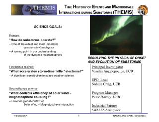
THEMIS T IME H ISTORY OF E VENTS AND M ACROSCALE I NTERACTIONS DURING S UBSTORMS RESOLVING THE MYSTERY OF WHERE, WHEN AND HOW AURORAL ERUPTIONS START THEMIS Instrument Critical Design Review – SST Material February 19 - 20, 2004 University of California, Berkeley.

E N D
THEMIS • TIME HISTORY OF EVENTS AND MACROSCALE INTERACTIONS DURING SUBSTORMS • RESOLVING THE MYSTERY OF WHERE, WHEN AND HOW AURORAL ERUPTIONS START • THEMIS Instrument Critical Design Review – SST Material • February 19 - 20, 2004 • University of California, Berkeley
SST SubsystemCritical (Peer) Design Review Davin Larson, Thomas Moreau, Ron Canario, Robert Lee, Jim Lewis, Mario Marckwordt, Rober Abiad, Jianxin Chen… UCB
Overview • Solid State Telescope (SST) • Requirements and Specifications • Block Diagram • Mechanical Design • Detectors • Collimation • Magnets • Attenuator (aka shutter, door) • Detector placement / FOV issues • Mass estimates • Electrical Design • DFE – (Detector Front End) • DAP – (Data acquisition and Processing) • Power Estimates • Testing and Calibration • Schedule • Issues From PDR
Science Requirements • SST-1: The SST shall perform measurements of the tailward-moving current disruption boundary speed using the finite gyroradius technique (4.1.1.2, 4.1.1.5). • SST-2: The SST shall measure the time-of-arrival of superthermal ions and electrons of different energies emanating from the reconnection region to determine the Rx onset time (4.1.1.3, 4.1.1.5). • SST-3: The SST shall compute the partial energy moments due to the superthermal ions and electrons in the magnetotail plasma sheet (4.1.1.3, 4.1.1.6, 4.1.1.7, 4.1.1.9, 4.1.1.10). • SST-4: The SST shall obtain measurements of ion and electron distribution functions with one spin time resolution (<10sec required) (4.1.1.2, 4.1.1.3). • SST-5: The SST shall measure energetic electron fluxes as close to Earth as 6RE geocentric, at all local times. (Radiation belt science- tertiary objective – achieved by nominal design). • SST-6: The SST shall measure energetic ions in the solar wind, at the magnetopause and in the magnetosheath (Dayside science – secondary objective – achieved by nominal design). From PDR
Performance Requirements • SST-7: The SST shall measure energetic particles over an energy range of 30-300keV for ions and 30-100keV for electrons found in the magnetotail plasma sheet (SST-1, SST-2). • SST-8: The SST energy sampling resolution, dE/E, shall be better than 30% for ions and electrons (SST-1, SST-2). • SST-9: The SST shall be capable of measuring differential energy flux in the range from: 10^2 to 5x10^6 for ions; 10^3-10^7 for electrons (keV/cm2-s –st- keV) whilst providing adequate counts within a 10 second interval. (exact values TBD) (SST-1, SST-2) • SST-10: The SST shall measure over 90o in elevation with a minimum resolution of 45o (SST-1, SST-2, SST-3, SST-4). • SST-11: The SST shall have an azimuthal resolution of 45o (SST-1, SST-2, SST-3, SST-4). • SST-12: The SST shall supply the high energy partial moments at one spin time resolution (SST-3) • SST-13: SST calibration shall ensure <20% relative flux uncertainty over the ranges defined above (SST-1, SST-2). From PDR
Overview • Solid State Telescopes: • Measure Energetic Electrons and Ions • Energy Range: • H+: 25 keV to 6 MeV (possible ~2 MeV) • Electrons 25 keV to ~800 keV • Angular Coverage: • Theta • 4 look directions (+55, +25, -25, -55) • Resolution: ~ 30 deg FWHM • Phi • 32 sectors • Resolution: ~20 deg FWHM • Geometric Factor: ~0.1 cm2-ster (~1/3 of WIND) • Pinhole Attenuator: Cuts geometric factor by 64 From PDR
Block Diagram IDPU Sensor Unit 1 (2 DFEs A&B) SST DAP Board ETC Board DCB Sensor Unit 2 (2 DFEs A&B) From PDR
Sensor Units • Each sensor unit is a: • Dual-double ended solid state telescope • Each double ended telescope (1/2 sensor) has: • Triplet stack of silicon solid state detectors • Foil (on one side) • Filters out ions <~350 keV • Leaves electron flux nearly unchanged • Magnet / Open side • Filters out electrons <400 keV • Leaves ion flux nearly unchanged • Mechanical Pinhole attenuator • Reduces count rate during periods of high flux • Reduces radiation damage (caused by low energy ions) during periods of high flux • Collimators • Preamplifier / shaping electronics From PDR
Progress Summary • We’ve come a long way since PDR • ETU Design Frozen ~12/31/2003 • DFE Board: • Schematics Completed • Layout Completed (~2 Weeks) • Board Procured (~1 Week) • Loading/Assembly ??/??/???? (2-3 Days) • Detector mating • Preliminary Electrical Testing Completed 04/05/2004 • DAP Board: • Schematics Completed ~01/05/2004 • Layout Completed ??/??/???? (~3 Months) • Board Procured ??/??/???? (~1 Week) • Board Loaded 04/05/2004 (~2 Weeks) • Testing Started on 04/05/2004, still in progress
Progress Summary • Sensor Mechanical Summary • All ETU parts designed and produced • (Except –50 C Thermostat - will use Hessi spare) • All parts fit checked. • Attenuator cycle Test #1 Complete (44,000 cycles) • Electrical/Mechanical Mating complete – • Functional testing completed.
RFA Responses • RFA #: UCB-6 Instrument: SST • RFA Title: SST Operating Temperature • Review: UCB Instrument EPR Date of Review: October 15-16, 2003 • Reviewer: Shelley Organization: Self • Recommended Action: • Take all practical steps to reduce average operating temperature of the SST instrument or at least its sensor elements. • Rationale: • The thermal analysis indicated an average operating temperature of 25C with a wide variation around that average. For noise levels consistent with the desired performance of this instrument, operating temperatures should be closer to 0-10C. • Response: • Nominal operating temperature is –20 C and can be adjusted pending future testing.
RFA Responses • RFA #: UCB-7 Instrument: SST • Review: UCB Instr EPR Date of Review: Oct 15-16, 2003 • Reviewer: McCarthy Organization: U. Wash. • Recommended Action:Reconsider the following design decisions: • Changing the sweep magnet to better exclude 250-400 keV electrons. - Done – 50gm/sensor mass penalty • Operating the detectors at an average temperature 0 C instead of 25 C. - Done • Increasing the ion energy range to include the 6 MeV calibration point. – Final decision still pending test results • Use of high-Z materials (tungsten) near the detectors should be evaluated in terms of locally generating bremsstrahlung x-ray background. – Baffles are BeCu.SmCo magnets shielded by Al. • Sun glints not only temporarily blind the particle detectors, but preamp can saturate and require additional time to recover. This effect to be measured, especially with their thinner dead layers. No Change yet
Sensor Unit Schematic Foil Detector Al/Polyamide/Al Foil Thick Detector Open Detector Foil Collimator Open Collimator Attenuator Attenuator Sm-Co Magnet From PDR
Sensor Cross Section Foil Collimator Attenuator Foil Detector Stack Magnet Attenuator Open Collimator From PDR
Detector Pixelation • Detectors similar to STEREO/STE • Produced at LBNL/Craig Tindall PI Active area 5 mm Guard ring 10 mm Additional Pixels not used for Themis From PDR
Previous Design (from PDR) +35 V ~200 A Polysilicon +5 V F n F Out p 225F GND Pixelated side ~1200 A Dead layer p n T T Out 225F n p O p O Out 225F n ~200 A Polysilicon + ~200 A Al @+35 volts 300 micron thick detectors
New Design -35 V ~200 A Polysilicon +4.5 V F n F Out p 225FB -2.5 V Pixelated side ~1200 A Dead layer F Test in p n T T Out 225FB n p T Test in O p O Out 225FB n Outside Grounded O Test in ~200 A Polysilicon + ~200 A Al 300 micron thick detectors
ETU Sensor Testing ETU Sensor with Cd109 source ~7 keV FWHM Resolution Test Pulser 22-25 keV photons 88 keV photons
ETU Sensor Testing ETU Sensor with Am241 source ~7 keV FWHM Resolution Test Pulser 14 & 17.5 keV photons (not resolved) 59.5 keV photons
SST MECHANICAL Robert K. Lee
SST Mechanical Design • Solid State Telescope (SST) • Mechanical Requirements • Mechanical Design • SST Sensor Unit Buildup • Sensor Unit Mounting Using Kinematic Flexures • Attenuator Actuation • Attenuator Control • Analysis Results • Attenuator Mechanism • Modal Analysis • Quasi-Static Acceleration • Attenuator Mechanism Cycling Test • Electronics and Cabling • Mass Summary
SST Mechanical Design • Mechanical Requirements • SWALES Mechanical Verification Specification 1c • Radiation shielding thickness driven by dose depth curve • Total subsystem mass ~ 1.4 kg (Mass estimate/allocation increased) • Two SST sensors • DAP electronics board with shielding (Mass allocated to IDPU) • Harness • Nitrogen purge required (prior to fairing placement) • Attenuator actuation must complete motion < 1 minute • Attenuator used approximately 20 times per day • Designed to allow easy removal of DFE (electrical) assembly
SST Mechanical Design • SST Sensor Unit Buildup • DFE Board Subassembly • Magnet-Yoke Subassembly • Attenuator-Actuator Subassembly • Collimators • Support Structure • Bi-Directional FOV • Sensor Unit Mounting Using Kinematic Flexures • Attenuator Actuation • Linear Actuators • Position Switches • Attenuator Control • Electronics and Cabling • DAP Board • Harness • Mass Summary
SST Mechanical Design • DFE Board Subassembly BeCu Gasket (3) Detectors (4) KaptonHeater Spring Clamp PEEK Spacer (4) Spring Plate (2) Kapton Flex-Circuit (4) AMPTEK Shield Thermostat • Detector Board Composition (exploded view)
SST Mechanical Design • Typical Electrical Connection Between Detector and Flex-Circuit Wirebond Loop (NOT to scale – actual loop height < 300 micron) Kapton Flex-Circuit Detector (pixelated side)
SST Mechanical Design • DFE Board Subassembly Relative Positions • (2 per sensor) Detector Stack Subassembly Foil Frame Multi-Layer Circuit Board (62 mil thickness) AMPTEK Shielding Thermostat
SST Mechanical Design • Magnet-Yoke Assembly Co-Fe Yoke (2) Sm-Co Magnet (4) (currently not visible) Aluminum Magnet Cage
SST Mechanical Design • Attenuator Assembly SMA Lever (2) Attenuator (4) Cam (2)
SST Mechanical Design • Actuators and Position Switches Honeywell SPDT Hermetically Sealed Switch (2) SMA Actuator (2)
SST Mechanical Design • Two Collimators Per Side Ion Side Electron Side
SST Mechanical Design • Four Collimators Per Sensor Ion Side Electron Side Electron Side Ion Side
SST Mechanical Design • Support Structure • (back section) Rigid Mounting Flange Electrical Connector Bottom Closeout Panel
SST Mechanical Design • Support Structure • (front section) Rigid Mounting Flange Kinematic Flexure (2)
SST Mechanical Design • Bi-Directional Fields-of-View
SST Mechanical Design • Sensor Orientation Relative to Spacecraft Bus
SST Mechanical Design • Sensor Unit Mounting Using Kinematic Flexures • Each sensor mounted to spacecraft panel at three points • One rigid mounting flange • Two mounting flanges with kinematic flexures • Allows relative motion due to CTE differences between sensor structure and spacecraft panel • Predicted expansion differential along instrument axes with 120 ºC temperature gradient: • X-Axis: 0.006” (0.15 mm) • Y-Axis: 0.013” (0.33 mm) • Flexure dimensions sized to keep maximum bending stresses below 6061-T6 yield strength • Factor of Safety (F.S.) > 1.4 per NASA-STD-5001
SST Mechanical Design • Attenuator Actuation – CLOSED position Honeywell Switch (compressed-position) Honeywell Switch (extended-position) SMA Actuator (retracted) SMA Actuator (extended)
SST Mechanical Design • Attenuator Actuation – OPEN position Honeywell Switch (extended-position) Honeywell Switch (compressed-position) SMA Actuator (extended) SMA Actuator (retracted)
SST Mechanical Design • Attenuator Control – CLOSED to OPEN (INITIAL) SST Sensor PCB PCB +5V +5V CLOSE Attenuator OPEN Attenuator BACK SMA FRONT SMA (ACTIVE) NO NO GND GND FREE COMPRESSED C C SPDT Switch NC NC Monitor Monitor LOW HIGH
SST Mechanical Design • Attenuator Control – OPEN to CLOSED (INITIAL) SST Sensor PCB PCB +5V +5V OPEN Attenuator CLOSE Attenuator BACK SMA (ACTIVE) FRONT SMA NO NO GND GND COMPRESSED FREE C C SPDT Switch NC NC Monitor Monitor HIGH LOW
SST Mechanical Design • Attenuator Control – Switch Activation Switch Roller during compressed-position Switch Toggle/Transition Cam Radius Switch Travel Length Switch Roller during extended-position Cam Rotation Angle Note: Sketch NOT drawn to scale
SST Mechanical Design • Analysis Results - Attenuator Mechanism • SMA pull-force of 125 grams • Mechanism required force < 42 gram => F.S. > 3.0
SST Mechanical Design • Analysis Results - Modal Analysis • ALGOR FEMPRO Version 13.30 • First Mode @ 600 Hz • Second Mode @ 1200 Hz • Third Mode @ 1550 Hz • Modal frequencies > Delta II minimum levels Finite element model with mass simulators
SST Mechanical Design • Analysis Results – Quasi-Static Acceleration • ALGOR FEMPRO Version 13.30 • 40g load along each instrument axis • X-axis maximum stress: 3040 psi • Y-axis maximum stress: 1730 psi • Z-axis maximum stress: 1440 psi • F.S. > 1.4 above yield strength for 6061-T6 X Axis Load Y-Axis Load Z-Axis Load
SST Mechanical Design • Attenuator Mechanism Cycling Test • Run over 40,000 cycles • Pivot shaft (303 Stainless) showed significant abrasion damage on contact surfaces with sapphire bearings • Subsequent shafts to be treated as follows: • Titanium Nitride (TiN) coating to increase hardness • Tungsten Disulfide (WS2) coating for dry film lubrication • Required SMA stroke reduced from 3.5 mm to 3 mm for additional operating margin (maximum stroke: 4 mm) • Mechanism test will be performed again with modified components on ETU (late April 2004) with minimum target of 150,000 cycles • Target values based on 10 times expected number of actuations on-orbit • Cycle counting will not be necessary for flight components
SST Mechanical Design • Linear Actuators • Shaped Memory Alloy (SMA) actuator • Single direction 125 gram pull-force • Required force < 42 gram => F.S. > 3.0 • Operating temp range: -70°C to +75°C Extended Position Relative Size (commercial model shown) Retracted Position
SST Mechanical Design • Position Switches • Honeywell miniature hermetically sealed switches • Single-Pole-Double-Throw (SPDT) • Operating temperature range: -65°C to +121°C • Exceeds MIL-S-8805 shock and vibration requirements Roller Extended Position Compressed Position
SST Mechanical Design • Nitrogen Purge Connection • Nitrogen line is connected to SST purge fitting during pre-flight operations to purge instrument interior • Gas supplied at 5 psig • Regulated and filtered flow rate of 1 liter/hour Supply fitting Vent