Download
1 / 33
330 likes | 364 Vues
This lecture review covers Chapter 13, 21-30 multiple choice questions and Chapter 31-33 word problems in Physics. Topics include Displacement Current, Induced Magnetic Fields, Maxwell's Equations, EM Wave Properties, and Radiation Pressure. Learn about electromagnetic wave intensities, polarization, and energy transport mechanisms. Prepare for the final exam with key concepts in Physics.

E N D
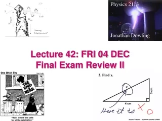
Physics 2113 Jonathan Dowling Lecture 42: FRI 04 DECFinal Exam Review II
Final Exam • 3:00PM – 5:00PM MON 07DEC PHYS 2113-1 (Moreno) is scheduled to take their exam in Lockett 9 PHYS 2113-2 (Gaarde) is scheduled to take their exam in Lockett 10 PHYS 2113-3 (Dowling) is scheduled to take their exam in Lockett 6 PHYS 2113-4 (O'Connell) is scheduled to take their exam in Lockett 15 PHYS 2113-5 and 6 (Abdelwahab) is scheduled to take their exam in Lockett 2 PHYS 2113-7 (Hansen) Last name starts with A - K: take their exam in Lockett 10, last name starts with L - Z: take their exam in Lockett 2
Final Exam • 100 PTS: CH 13, 21–30 / HW01-11This part will be 11 multiple choice questions one from each chapter. • 100 PTS: CH 31–33 / HW12-14This part will be three multiple choice questions and three word problems, one each from each chapter.
B ! B B Displacement “Current” Maxwell proposed it based on symmetry and math — no experiment! i i E Changing E-field Gives Rise to B-Field!
32.3: Induced Magnetic Fields: Here B is the magnetic field induced along a closed loop by the changing electric flux FEin the region encircled by that loop. Fig. 32-5 (a) A circular parallel-plate capacitor, shown in side view, is being charged by a constant current i. (b) A view from within the capacitor, looking toward the plate at the right in (a).The electric field is uniform, is directed into the page (toward the plate), and grows in magnitude as the charge on the capacitor increases. The magnetic field induced by this changing electric field is shown at four points on a circle with a radius r less than the plate radius R.
Example, Magnetic Field Induced by Changing Electric Field:
Example, Magnetic Field Induced by Changing Electric Field, cont.:
32.4: Displacement Current: Comparing the last two terms on the right side of the above equation shows that the term must have the dimension of a current. This product is usually treated as being a fictitious current called the displacement current id: in which id,encis the displacement current that is encircled by the integration loop. The charge q on the plates of a parallel plate capacitor at any time is related to the magnitude E of the field between the plates at that time by in which A is the plate area. The associated magnetic field are: AND
Example, Treating a Changing Electric Field as a Displacement Current:
Electric Field: Magnetic Field: Wavenumber: Wave Speed: Angular frequency: Vacuum Permittivity: Vacuum Permeability: Fig. 33-5 Amplitude Ratio: Magnitude Ratio: Mathematical Description of Traveling EM Waves All EM waves travel a c in vacuum EM Wave Simulation (33-5)
The Poynting Vector: Points in Direction of Power Flow Electromagnetic waves are able to transport energy from transmitter to receiver (example: from the Sun to our skin). The power transported by the wave and its direction is quantified by the Poynting vector. John Henry Poynting (1852-1914) For a wave, since E is perpendicular to B: In a wave, the fields change with time. Therefore the Poynting vector changes too!! The direction is constant, but the magnitude changes from 0 to a maximum value. Units: Watt/m2
EM Wave Intensity, Energy Density A better measure of the amount of energy in an EM wave is obtained by averaging the Poynting vector over one wave cycle. The resulting quantity is called intensity. Units are also Watts/m2. The average of sin2 over one cycle is ½: Both fields have the same energy density. The total EM energy density is then
EM Spherical Waves The intensity of a wave is power per unit area. If one has a source that emits isotropically (equally in all directions) the power emitted by the source pierces a larger and larger sphere as the wave travels outwards: 1/r2Law! So the power per unit area decreases as the inverse of distance squared.
Example A radio station transmits a 10 kW signal at a frequency of 100 MHz. Assume a spherical wave. At a distance of 1km from the antenna, find the amplitude of the electric and magnetic field strengths, and the energy incident normally on a square plate of side 10cm in 5 minutes.
Radiation Pressure Waves not only carry energy but also momentum. The effect is very small (we don’t ordinarily feel pressure from light). If light is completely absorbed during an interval Δt, the momentum Transferred Δp is given by F and twice as much if reflected. A Newton’s law: I Now, supposing one has a wave that hits a surface of area A (perpendicularly), the amount of energy transferred to that surface in time Δtwill be therefore Radiation pressure: [Pa=N/m2]
EM waves: polarization Radio transmitter: If the dipole antenna is vertical, so will be the electric fields. The magnetic field will be horizontal. The radio wave generated is said to be “polarized”. In general light sources produce “unpolarized waves”emitted by atomic motions in random directions.
EM Waves: Polarization Completely unpolarized light will have equal components in horizontal and vertical directions. Therefore running the light through a polarizer will cut the intensity in half: I=I0/2 When polarized light hits a polarizing sheet, only the component of the field aligned with the sheet will get through. And therefore:
Example Initially unpolarized light of intensity I0 is sent into a system of three polarizers as shown. What fraction of the initial intensity emerges from the system? What is the polarization of the exiting light? • Through the first polarizer: unpolarized to polarized, so I1=½I0. • Into the second polarizer, the light is now vertically polarized. Then, I2 = I1cos2(60o)= 1/4 I1= 1/8 I0. • Now the light is again polarized, but at 60o. The last polarizer is horizontal, so I3 = I2cos2(30o) = 3/4 I2 =3 /32 I0 = 0.094 I0. • The exiting light is horizontally polarized, and has 9% of the original amplitude.
Completely unpolarized light will have equal components in horizontal and vertical directions. Therefore running the light through first polarizer will cut the intensity in half: I=I0/2 When the now polarized light hits second polarizing sheet, only the component of the field aligned with the sheet will get through.
Reflection and Refraction When light finds a surface separating two media (air and water, for example), a beam gets reflected (bounces) and another gets refracted (bends). Law of reflection (Light Bounces): the angle of incidence θ1 equals the angle of reflection θ’1. θ1 = θ’1 n is the index of refraction of the medium. In vacuum, n = 1. In air, n ~ 1. In all other media, n > 1.
Away ✖ Can’t go past normal ✖ Toward ✔ In each case going from less to greater.
Chromatic Dispersion The index of refraction depends on the wavelength (color) of the light. Rainbow!