Download

1 / 53
610 likes | 1.53k Vues
Hyatt Regency Walkway Collapse “A Personal Perspective & Insight”. Presented By: Jack D. Gillum, P.E. Two Walkways Collapsed 114 People Lost Their Life Failure of Hanger Rod Connection (4th Floor). Kansas City Hyatt July 17, 1981. OWNER: Crown Center Redevelopment Corp. DESIGN TEAM:

E N D
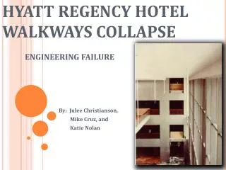
Hyatt Regency Walkway Collapse“A Personal Perspective & Insight” Presented By: Jack D. Gillum, P.E.
Two Walkways Collapsed • 114 People Lost Their Life • Failure of Hanger Rod Connection (4th Floor) Kansas City Hyatt July 17, 1981
OWNER: Crown Center Redevelopment Corp. DESIGN TEAM: ARCHITECTS Patty Berkebile & Nelson Herbert Duncan Monroe - Lefbvre Marshal & Brown STRUCTUAL ENGINEERS: Gillum Colaco Concordia Project Management Havens Structural Steel Eldridge & Son Construction General Testing Laboratories The Team Owner/Design & Construction Team
Hyatt General Layout Entrance
Kansas City Hyatt Entrance to Hotel and Atrium
Bridge Plan Tower 29 4TH & 2ND FLOOR BRIDGES N 3RD FLOOR BRIDGE 29 29 29 Function Block
Atrium Roof Plan 29’-Typical 15’-2+” 4@ 29+=120’
Physical description – Bridge Plan Guest Tower Connections Des. by Fabricator 29 29 N 29 Atrium 29 Function Block
CHRONOLOGY OF EVENTS Major Events Occurring DesignPhase Fast Track Project Project Engineer Leaves Project Designer Leaves QC Problems during construction SE request to perform inspection: Refused Screen Wall Changes Bridge Hanger Changes Portion of Atrium Roof Collapsed Walkway Bridge Collapsed
CHRONOLOGY TIMELINE • 1976 - MID 1977 • Schematic Design (750 Rms, 35 Flr, 120’ Atrium • Jan 1978 • Fast-Track Design/Construct-Contract w/GC
CHRONOLOGY TIMELINE • April 1978 • Structural Contract “All Structural Eng. Serv.” • Jan - Aug 1978 • Design continues during construction • SE requested owner to be retained for inspection servicesDENIED
Physical description – Bridge Plan Guest Tower Connections Des. by Fabricator 29 29 N 29 Atrium 29 Function Block
Design Phase – Bridge Connection Evolution • No rod size • No reaction • No rod strength
Design Drawings v.s. Shop Drawings • Changes During Shop Drawings • Requested two rods by phone • Approved by phone with caveat “submit through channels” The shop drawings are checked by a technician who did not work on the project. Questions are raised about the strength of the rod
CONNECTION AS BUILT THIS CONNECTION WAS NEVER DRAWN NOR SUBMITTED FOR APPROVAL
Chronology (Continued) Summer 1979 • Erection of Steel for Atrium • Contractor omits embedded inserts in Concrete for steel connection • Needs to be modified by Engineer • Owner (again) refuses Engineer request for field representation third time • Owner fires testing lab due to poor performance during inspection of const.
Construction Collapse / Design Checks Problems at connections along expansion joint at the interface between steel and concrete structures
Chronology (Continued) October 1979 • Atrium roof collapse • Deficiencies in modified construction at concrete/steel interface discovered • Engineer initiates in-house check of Atrium roof • Outside Peer Review Initiated & Completed
ATRIUM ROOF:STEEL TO CONCRETE CONNECTIONS Engineer Designed & Modified
Construction Collapse / Design Check Problems at the screen wall are uncovered EOR in-house check EOR issues correction details for screen wall Screen wall corrections are made in the field Problem with the bridge connection is not discovered Independent design check and field inspection does not uncover either error
Design Phase – Screen Wall Changes *DURING THE SHOP DWGS Horizontals supporting splice points are moved for architectural reasons. The splice points on the truss drawings are not moved
Chronology ( Continued ) Late-1979 to July 1980 Gen’l Contractor goes bankrupt and Crown Center takes over as contractor using personnel of Gen’l Contractor July 1980 • Hotel Opened July 17, 1981 • Walkway bridges collapse
Bridge Collapse Double rod connection failed Connection that failed was never shown on ANY drawings!! Engineering or Detailer Connection that failed was never designed
Why Did It Happen? Combination of :Personnel Errors • Design Deficiencies • Inadequate Oversight & Review Process • Missed opportunities to discover error • Poor Communication
Standard of Practice (During this period of time 1950’s -1980’s)Standard of Practice in the profession was for the Fabricator to design and detail all structural steel details (includes design of connections) unless detailed by the Structural Engineer Standard Originated with the fabricator’s to insure a least costly and practical connection from the fabrication viewpoint
Factors That Contributed to the Collapse • Fast Track Process • Architectural design changes & conceptual re-designs • Drafting Errors • Checking errors-Shop Drawings • Invalid initial design concept of hanger Senior engineer personnel changes • Phone changes w/o follow-up by detailer or engineer in writing
Factors That Contributed to the Collapse • No Structural Site Representation (Refused several times) • Engineer Relied (ASSUMED) based on past projects on design of connections by Fabricator, w/no follow-up by Project Manager
Factors (Continued) • Fabricators in-house engineer transferred fabricator’s partial shop dwgs to outside firm who assumed connection was designed • Engineers technician, checked piece size but not connection. (Not Drawn or submitted) • Outside Peer Review didn’t check shop dwg
Factors (Continued) • “Design Check” questions answers not verified • In-house design check questions following atrium collapse were not verified. No Follow Up • Poor Testing & Inspection
Warning Signs!!!Never Transmitted to Engineer • Walkway deflection of 3/4” observed by workman who notified architect’s site representative seven weeks B4 July 80 opening. No Follow Up • General Contractor's attorney reported : “….from date of full dead load loading of 4th and 2nd floor bridges (July 1, 1980), box beams began to distort and distortions were visible to naked eye.”
Warning Signs!!!Never Transmitted to Engineer • Handrail Deflection noted on punch list of 130 items (Aug, 1980) • Feb 1981 Box Beam Deformations noticed by dry wall installer. (No one notified)
What Should Have Occurred ? • Single Rod Concept detail on engrs dwg noted as conceptual only • Fabricator design connection • Picked up during shop dwg check as not designed • After atrium collapse picked up during design re-check which should have been a thorough design document check
What Should Have Occurred ? • EOR provide full time inspection • Engineer Notified of warnings! • Rundancy • All of above
Lessons Learned Procedures must be implemented that assure that all connections are designed by a competent professional Peer reviews and design checks should include a review of shop drawings
Lessons Learned When questions come up look at surrounding issues for related problems EOR should be retained to provide full inspection during construction of structure Owner needs on site qualified representation
Lessons Not Learned Design and construction is a collaborative process that requires professional integrity, judgment, and integrity on the part of all participants We have not yet clearly defined the nature of the design and construction process and the information flow that is required for success in all respects We have not learned to respect and teach the history of the profession and fully disseminate information of problems that occur
WHAT IS THE FUNDAMENTAL ISSUE? • WHO TAKES THE RESPONSIBILITY FOR ENSURING THE WHOLE OF THE PROJECT CONFORMS TO THE DESIGN INTENT AND THE SAFETY OF THE GENERAL PUBLIC ?
Where does the buck stop? ALL MEMBERS OF THE DESIGN TEAM ARE RESPONSIBLE FOR WHAT THEY DO! • Take the time to check your own work! • DON’T ASSUME SOMEONE ELSE WILL! Continuing Maintenance and Inspections by OWNER ! Final Responsibility? The Engineer of Record!!
What Has Been Done NY State Board of Regents Proposed Amendment (Adopted 6/96) • Only ancillary to main components • Clearly specified performance criteria • Performed by licensed professional • Primary Design Team must check & approve, i.e...“Each designer responsible for own work”
What Has Been Done (Cont’d.) States of Florida and Connecticut added legislation relative to checking shop drawings. (Both are different) Combined with NY, only these 3 states in 20 years have any legislation relative to who does what.
ASCE: “Quality in the Constructed Project”, 2000(After 20 years) FINALLY!!ASCE: “Quality in the Constructed Project”, 2000 (After 20 years) PP17.3.2: Shop Drawings for StructuralComponents Conn. design by Fabricator to tailor to fabrication methods EOR has authority & responsibility for overall Design of Project Fabricator responsible for connections & details
ASCE: “Quality in the Constructed Project”, 2000(After 20 years) FINALLY!!ASCE: “Quality in the Constructed Project”, 2000 (After 20 years) Complex Structures (Two Approaches OK) EOR performs complete engineering design (including conn.) Fabricator provides services of PE to design or supervise design of components not completely designed in the const.doc’s. EOR responsible to Ck shop dwgs and design for either method
CONFIGURATION MANGEMENT Strictly Regulated Industry by Government Regulations state that design, processes, documentation, changes and records must be managed This is up to Producer/Operator
CONFIGURATION MANGEMENT As the result of design problems,worker errors and equipment malfunctions of Three Mile Island and the Salem ATWS event in 1983, CM has continued to evolve and improve following the NRC Bulletin 79-14 CM, reinvented under CMII and ISO 10007 Quality Management (3 tier/8 step program) Adoption of Risk-Informed Baseline Inspection Program
Configuration Management (cont’d) • Non Regulated Industry Design and Construction have many similar problems Dissemination of problems (CR”s) and solutions to include CM processes and which includes all team members is important