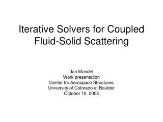
Coupled Fluid-Structural Solver
Coupled Fluid-Structural Solver. CFD incompressible flow solver has been coupled with a FEA code to analyze dynamic fluid-structure coupling phenomena CFD solver uses pressure splitting and orthogonal subgrid subscale stabilization to prevent non-physical behavior

Coupled Fluid-Structural Solver
E N D
Presentation Transcript
Coupled Fluid-Structural Solver • CFD incompressible flow solver has been coupled with a FEA code to analyze dynamic fluid-structure coupling phenomena • CFD solver uses pressure splitting and orthogonal subgrid subscale stabilization to prevent non-physical behavior • Structural solver suitable for large deformation analysis, including wrinkling of structural membranes • All coding has been done in C++ inside the KRATOS object-oriented development framework for multiphysics analysis • KRATOS allows for completely modular code design and ease of incorporation of new capabilities
KRATOS • An environment for implementing innovative computational methods • Under continual development at CIMNE specifically to address coupled problems • Based on Object Oriented Approach using C++ • Features a Python-Based programmable input • Featured coupling strategies: • STRONG COUPLING “SAFE” but often computationally expensive, requires iterative solving strategy • LOOSE COUPLING is often considered “UNSAFE”, computational efficiency is potentially very HIGH
Incompressible CFD Solver • ALE formulation • Orthogonal subgrid subscale stabilization • Choice of: • Second-Order Accurate Fractional Step solver • Monolithic solver
Structural Solver • Non-linear large displacement/deformation capability • Features advanced membrane elements including wrinkling • Total Lagrangian model
Change in fluid Boundary conditions Structural Deformation Change in the pressure field Coupled Fluid-Structure Interaction Problem • Boundary conditions for the fluid are not known until the structure displacement is calculated • BUT • Loads on the structure cannot be determined until the flow field has been solved for
Structural Prediction • Mesh movement step • Fluid Solution • Structural Correction Prediction is done by SOLVING the structure subjected to a predicted pressure field (the simplest choice is the pressure at the end of the step before) Coupled “Fractional Step” Strategy It follows the same rationale as the fractional step (pressure segregation) procedures used for the solution of the Navier-Stokes equations
Error due to the coupling algorithm Assuming that the pressure can be described in the form and that the structural time integrator can be expressed in a form of the type it is possible to express the solution of the coupled problem “in the future” as where yn is an error term, for the coupling procedure to be stable this term must not grow without bounds
The amplification factor of the error term is convergence is achieved when the amplification factor is less than one Remark: The amplification factor does not depend on the particular time integration scheme selected The basic scheme: can be replaced with the procedure remains consistent, as there is no change when Δt→0
By choosing an appropriate value for the procedure can be made stable irrespective of the mass ratio • A suitable value can be estimated from the structure of the stiffness matrix of the fluid problem Inserting the assumed form of the pressure into the modified algorithm we have now the scheme is stable when
Example: Flag Flutter Fvon Karman = 3.7Hz Fcoupled simulation = 3.05Hz Fcoupled experiment = 3.10Hz
PUMI 3D CFD Solver Capabilities Overview: • Finite element unstructured compressible flow solver • Edge-based data structure for minimum memory footprint and optimum performance • Second order space accuracy • Explicit multistage Runge-Kutta time integration scheme • Convective stabilization through limited upwinding • Implicit residual smoothing for convergence acceleration • Parallel execution on shared memory architectures via OPEN-MP directives
Algorithm Overview NS equations in conservative form
Weak form of the NS equations Finite element discretization Weak semi-discrete form
The numerical fluxes are now approximated by by introducing the mass matrix, the last expression can be solved for the time derivatives of the nodal variables
To improve computational efficiency the residual is split two parts (from this point on, no sum is assumed on i, and all sums on j are carried out for j≠i) integrating by parts and rearranging the expression must now be symmetrized to realize the benefits of the edge data structure
using the shape function property and after some manipulation
Please remark that thus, only one coefficient need be stored for each internal edge (pair of connected nodes, i.e. nodes belonging to the same element) The scheme is conservative because for any given edge e connecting two internal nodes i-j, the total contribution the residual is zero When solving a viscous problem, nodal values the solution gradient are required to obtain the nodal diffusive fluxes. These can be recovered by means of a smoothing step. Using the regular FE interpolation for the gradients we set
where the matrix represents the positive flux jacobian along the direction of the edge, evaluated at the Roe average state between states i and j This scheme, while stable, provides only first order space accuracy. The amount of artificial dissipation must be reduced. Two additional states i+ and j- are introduced It is well known that the basic Galerkin discretization is inherently unstable (it is equivalent to a centered difference scheme). To overcome this limitation the interface fluxes are modified according to Roe’s upwind scheme
from the backward and forward extrapolated differences the new interface states are calculated as where the parameter k controls the degree of approximation. Near discontinuities the scheme must revert to first order. This is accomplished by limiting the degree of extrapolation
There are many possible choices for the limiting parameter. As an example, we show here the van Albada limiter Remark: It is in theory possible to achieve a higher accuracy by calculating the interface fluxes using the extrapolated values, i.e. however there is usually little difference in practice, so this enhancement can de omitted without noticeable loss of accuracy
Time integration is performed using a n-stage Runge-Kutta scheme this scheme is conditionally stable, the nodal allowable time step is calculated as hi being the nodal size, n the maximum fluid diffusivity and CFL the allowable Courant number
By means of implicit residual smoothing the allowable time step can be increased which is solved using Jacobi iterations Time derivatives (and solution gradients) can be solved for very efficiently using the following iterative process
Example: Transonic flow over a commercial airliner test model