Download
1 / 31
310 likes | 418 Vues
This project focuses on designing a charge regulator for photovoltaic systems, offering efficient battery charging with overcharging and deep discharging protection. Features, types of photovoltaic cells, and circuitry details are explored, highlighting advantages and disadvantages.

E N D
Battery Charge Regulator for a photovoltaic power system using microcontroller By: Raed Wa’el Ennab & Raja Sa’ed Anabtawi Supervised by : Prof. Marwan Mahmoud
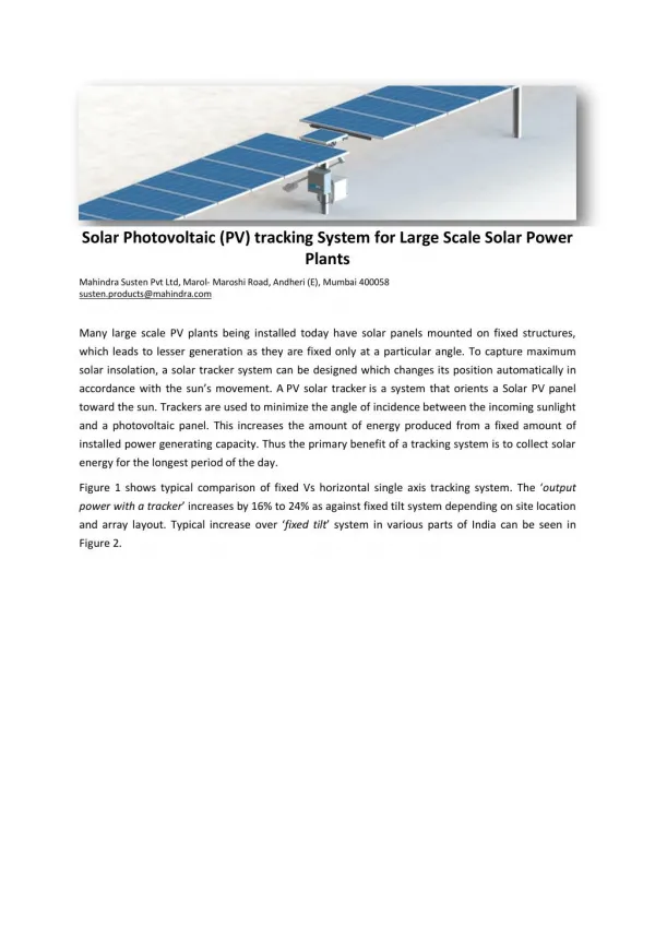
Introduction Since the beginning of the oil crises, which remarkably influenced power development programs all over the world, massive technological and research efforts are being concentrated in the field of renewable energy resources. In the solar sector for electricity generation, greater attention is being given to photovoltaic conversion.
Features 1- Charge any rechargeable battery 12V, 24V. 2- Supply any low dc load. 3- Solar-powered. 4- Displays charging status. 5- Polarity checking. 6- Current Limiting.
Advantages and Disadvantages: The advantages are: 1- Renewable resource. 2- Silent. 3- Non-polluting. 4- Little maintenance. 5- easy to install. 6- Reliability. And the disadvantages are: 1- Very expensive. 2- No work at night.
Block Diagram Solar Panel Regulator PIC Load Lead Acid battery
Photovoltaic cells: Solar Panel Regulator PIC Load Battery In our design, the solar panels will function as a power supply to our circuit. It will convert the sun radiation to voltage and current. types of photovoltaic cells : 1-mono-crystal silicon. 2-Polycrystal silicon . 3-Amorphous silicon (thin film silicon).
number of cells The output voltage of a module depends on the number of cells connected in series. The module we used was 25 cell connected in series.
A Typical Current-Voltage Curve for a Module at (1000)W/m^2 & (500)W/m^2
Photovoltaic Arrays: Series connection Parallel connection
Charge Regulator : Regulator The solar charge regulator main task is to charge the battery and to protect it from overcharging and deep discharging. Deep discharging could also damage the battery. Kind of charge regulators: 1-Simplest switch on/off regulators. 2-PWM ( Pulse Width Modulation). 3-MPPT charge regulator (Maximum Power Point Tracking).
Solar panel Regulator PIC Load Lead Acid Battery Lead acid Battery 1- We are going to work on six-cell lead-acid batteries. 2- Voltage/cell 1.75-2.4 V. 3- Battery charge. 4- Battery efficiency. 5- Minimum Voltage.
Lead acid battery In our project, the circuit we built has two leds; red one and green one.
circuitry • +S • S
Circuitry • when the voltage is lower than 14.4 V the comparator (IC3) allows a high negative output signal to switch on the PNP transistor (Q1). • During charging, the battery voltage increase until it reaches the 14.4 V value. At this voltage, the transistor (Q1) will be switched off. • N1 and N2 from the IC4001 are utilized as pulse oscillators for the purpose of testing. • In this short period, transistor Q2 will be switched on, and a current will flow from the emitter to the collector of Q2.
Then the comparator (IC2) compares the battery voltage with the open-circuit voltage of the solar generator. • The main objective of using the pulse generator is to control the voltage of both the solar generator and the battery continuously. • The objective of the comparator (IC5) is to control the battery voltage during the discharging mode
two MOSFET transistors were utilized instead of one - To make the prevention of the battery discharging via the solar generator as strong as possible. - The temperature of the two transistors, due to the voltage drop across them, is divided equally between them. - Increasing the reliability of the controller since one transistor can perform the task of the other in case of its failure. - This arrangement protects the controller from failure whether it is connected to the solar generator first or to battery.
Features of The Locally developed Battery Control Unit (BCU) - Protects battery against overcharging: the unit controls the charging current via a regulated impulse, thus preventing harmful overcharging. - Protect the battery against deep discharging: the unit controls battery discharge by means of bistable load relay. • - If the battery charge drops bellow a predetermined voltage threshold, the relay automatically disconnects the load, this is indicated by a red light- emitting diode (LED). - The unit is protected against battery reverse polarity via a diode (D4).
Start Read the battery Voltage Read the voltage fro the regulator No 3.645<V.batt< 4.166 & Vreg.>4.340 No Yes 4.167<Vbatt.<5.0 & Vreg.>4.340 Out to the battery from the regulator Yes Out to the load from the Regulator Flow chart
Here we used the DAC to convert the digital output from the PIC to Analog.
Results I-V Characteristic At G=950 w/m2
Results Fill factor and efficiency: The Imp = 350 m A and the Vmp =15 volt So the max power point = 15*.350= 5.25 watt. The fill Factor: FF= (Imp*Vmp)/ (Is.c*Vo.c) = (15*0.350)/ (19*.4) = 70% The efficiency: Eff= P.opt/ A.Ee Eff=5.25/ 0.3*0.3*950 =6.1% All calculations are at G=950 w/m2
Problems we have faced: • 1- The output voltage was about 15 volts, and the PIC accept only 5 V maximum. • 2- The radiation from the sun was different from day to another. 3- The wires we used first were the thin wires so when the current passed these wires got hotter.
Conclusion and Recommendation: -From the technical and economical viewpoints, it can be said that the PV technology has attained an acceptable degree of operational efficiency and reliability. -Module degradation seemed to be a problem in amorphous PV technology. -The tested amorphous PV module showed power degradation between 16.4% and 39% at the end of the first year testing period. -if we have more time we could program the PIC with a program that can drive a stepper motor and rotate it as the max radiation from sun and that by using photo sensors.